


Article about Temperature Control with a PID Controller
I. I. Introduction
and then be able to apply them in their own challenges of temperature control.
II. Project Concept and Design
This project involves several important design considerations.
It is important to first define precisely the objective of control. What is the exact regulation required? It could be the temperature in a sealed, small enclosure or the liquid temperature within the vessel. Or it might even be the surface temperature on an electronic component. This is because the nature of a controlled variable, or "load", has a significant impact on component design and system selection.
Second, it is necessary to determine the operating range desired.
The third design decision is the choice of actuator. This device adds or removes heat to reach the desired temperature. It is important that the actuator chosen be compatible with output capability of control system.
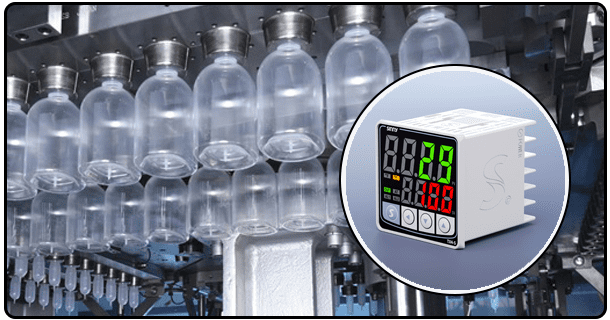
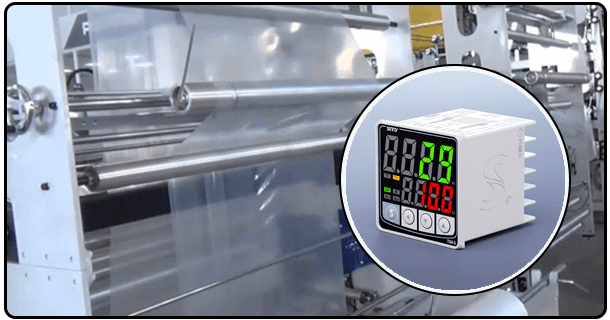
The fourth step is to select the right temperature sensor. Sensors must be able to accurately determine the temperature (or representative point) of the variable that is being controlled. The most common types are thermocouples which, while robust, can be used in a range of temperature conditions. However, they offer less accuracy. Resistance Temperature Detectors, also known as RTDs, have higher accuracy, stability and accuracy, especially over a wider range. And thermistors for applications requiring a high level of sensitivity. The selection of these types, as well as other options such a thermocouple amplifiers and integrated sensor modules depends on several factors, including the temperature range required, the accuracy needed, the response time necessary, the cost involved, and the ease with which the module can be integrated into the controller. In this project, you should choose a particular sensor type, such as an NTC thermometer or K-type module, and briefly justify your choice.
This diagram explains how the sensor gives feedback to the controller. It also demonstrates how the controller uses this data and generates the output signal that controls the actuator to influence the temperature of the load.
III. Selecting and Sourcing Components
The next step is to identify and select the hardware required. To ensure that nothing is overlooked during procurement, a list is created of all the necessary components. Core components include a computer, also known as a microcontroller. This is the engine that runs the entire system. It's often selected for the balance between processing power and ease-of-use, along with the available I/O ports (e.g. Arduino boards such as Uno, Nano or Raspberry Pi, or ESP32 Modules). Another option is a PID module, which integrates the PID algorithms and provides simplified interface options. However, implementing PID using libraries on a Microcontroller is also an educational and viable approach.
For accurate feedback, it is important to select a suitable temperature sensor during the design phase. It is also necessary to specify the temperature actuator. This can be a Peltier module or resistive heater. Hobbyists often use relatively low-power actuators, but they must still be able to influence the temperature range of their load. Separate power supplies for the microcontroller and sensor are required to ensure that each component is receiving the right voltage and current. If the microcontroller output pins are not able to handle the current drawn by the actuator, a relay module may be required. The list also includes basic components such as a prototype breadboard, jumper cables for connection, and a possible enclosure to house the system.
To source these components, you need to identify reliable suppliers. Adafruit SparkFun Digi-Key Mouser or Amazon are all online retailers that specialize in electronic components. Original equipment can be found on manufacturer websites.
IV. Installation and assembly of Hardware
Hardware setup is the phase that translates design concepts to a physical configuration. The hardware setup phase involves connecting each component according to its design. Each connection is given detailed instructions, with emphasis on adhering to component datasheets in order to avoid damage and to ensure reliability.
First, the sensor for temperature is connected. The sensor output pins are typically connected to the input pins of the PID module or microcontroller (e.g. VCC, GND and signal pins in the case of an analog sensor or signal pins with a digital one). For some sensor types and interfaces (such as digital sensors that communicate over I2C, SPI or I2C), pull-up resistors or resistance may be needed. For accurate readings, it is important to use the correct wiring.
The actuator will be connected next. Flyback diodes can be used across the coil terminals of the relay if you are driving inductive devices like motors and relays. This will protect the output pin on the microcontroller from spikes.
The powering of the system as a whole requires attention. The microcontroller, sensor, actuator, and relay module (if any) all require different voltages (e.g. 5V, 3.3V, or 12V, 24V, or even more for the actuator). The power supply must match the requirements of all components and be able to deliver enough current, particularly for the actuator. The connections should be made securely using connectors, soldered joints or insulating them to avoid short circuits. For initial prototyping and easy modification, breadboards can be a convenient option.
Software is the brain of the PID Temperature Control System, converting sensor data into actions to control the actuator. The development of this software requires several steps. It begins with the setup of the development environment. Installation instructions are included for the required software tools.
This is because the PID algorithm, itself, forms the core of the program. The code for the functions below must be written.
Read Sensor data: Implement code to read temperature values from the sensor. This could involve reading an analog voltage (using analogRead() on Arduino) or reading digital data (using Wire.beginTransmission(), Wire.requestFrom(), etc., for I2C sensors).
Implementing PID: Integrating PID equations in the code. Although one can write their own PID logic, it is recommended that beginners use a library such as PID_v1. It handles all the calculations internally and offers configuration options. The library requires that you define the gain types (Kp, Ki, Kd), the temperature setpoint, as well as the input measurement. The library calculates error (the difference in setpoints and measurements), uses PID to process this error, and then outputs a value.
Calculating Output Signals: Raw outputs from PID libraries often require scaling or interpretation. If you are using a heat relay, for example, it may be necessary to use the PID signal to adjust the duty cycle on a PWM signal. It could also be simply a digital number (0 or 1) to trigger the relay. The output could be a number sent to a DAC or directly controlled a PWM.
Actuator Control: In the final step, the output signal is used to control the actuator. The microcontroller can be controlled via the digital output pins or analog output pins for PWM, as well as a relay module.
Basic error Handling By implementing simple error handling such as a check for failures in sensor communications or the status of actuators, you can increase system robustness.
It is important to provide the complete structure of the code, or the minimum framework. This includes all comments that explain the function and purpose of the variables. Structure the code to make it easy to read and maintain. If you want to include display and user interface functions (e.g. showing setpoints, temperature and PID on an LCD), then there will be additional code required for the interfacing of the display module, as well as handling buttons inputs for setting setpoints.
VI. PID Tuning Process
The correct tuning of PID parameters (Proportional (P), Integrated (I) and Derived (D) is crucial to achieving effective temperature control. Before tuning, it is important to understand how the parameters affect the behaviour of the system. The proportional term (P), which directly impacts the output, is proportional to the error. (The difference between setpoint temperature and the measured temperature). If set to a higher value, the P term will respond more strongly to errors. However, it can cause oscillation or instability if too high. In the Integral term, past errors are accumulated over time. This constant adjustment is used to remove steady-state error. Excessive I actions can cause oscillations. The derivative term (D), which predicts the future error based on current errors, helps to reduce oscillations, improve system response times, and contribute to stability.
It can be difficult to find the best P, I and D values, which often require experimentation and close observation. Although there are automatic tune-up routines that can be integrated with PID modules and other controllers, it is important to understand the manual tuning process. Ziegler-Nichols is a common method for determining a system's Ultimate Gain and Ultimate Cycling Time. This involves increasing proportional gain until the oscillations are consistent in amplitude. Based on empirical formulas these values can be used to determine the initial value of P, I and D. This method may be hard to use for smaller projects or those with less predictability.
Practical manual tuning techniques for this project are usually more effective and feasible. It is common to begin with the Proportional. Start with a low value of P (e.g. P=1 and P=0.1), then observe how the system responds when you change the setpoint. Gradually increase P until you see the system oscillate. The point at which the system starts to oscillate gives an idea of what you will gain in the end. Alternately, you can start by using a P-value that is moderate and then adjust it according to your observations. After a P value has been found to provide a fast response, without oscillations that are excessive, you can introduce the integral term. Set Ki at a low value, e.g. Ki=0.1, and see if it improves the ability of the system to maintain the setpoint, eliminating slow drift. If drift continues, increase Ki slowly. Be sure to keep an eye out for new oscillations. The derivative term may be added at the end. Set Kd at a low value, e.g. Kd=0.01, and see if damping improves. Iterative tuning involves changing a parameter one at a time and observing how the system behaves. Then, further adjustments are made.
It is important to find a balanced system that responds rapidly to changes in the setpoint. The aim is for the system to reach the setpoint without overshooting, maintain a stable temperature around the setpoint and quickly recover from any disturbances. There are several tuning tips, including starting with P and moving on to I and D, watching for oscillation, overshoot and settling times, as well as making small adjustments. The final values of P, I and D must be saved in the program. If the microcontroller allows it, non-volatile storage can also be used.
VII. Test and Validation of System
After the hardware has been assembled and PID parameters have been tuned, it is important to test the system rigorously in order to ensure that the performance is as expected. Testing begins with basic checks. Turn on the system, and verify that the microcontroller runs the program. Also confirm that sensor readings and display are correct. Even if a controller's control signal has been initially set at a fixed level (e.g. fully on, off), check that the actuator is responding appropriately.
In order to perform the primary test, you will need to set the desired temperature via the interface of the system (e.g. a potentiometer or software settings if available). Watch the response of the system as it tries to maintain and reach this temperature. Monitoring the temperatures over time is best done using the software logging and plotting features, if they are available. The key performance indicators are the rise time, which is how quickly the temperature reaches its setpoint. Ideal response is for the system to be relatively quick, smooth, and maintain the temperature close to setpoint.
Introduce controlled disturbances to further test the robustness of your system. If the enclosure is controlled by the system, you can open it briefly to allow cooler air to enter and see how the system reacts. It should be able to detect the drop in temperature, and increase heating output if necessary to bring the temperature up to setpoint. If you are controlling the liquid temperature, add some cooler liquid and watch the reaction.
Review the data that has been logged (e.g. temperature graphs versus time). It is possible to analyze the performance of the system in greater detail, making it much easier to detect any problems, like persistent oscillations or slow responses, as well as failures to reach setpoints. The observations may require minor adjustments in the PID parameter, but the most significant tuning is usually reserved for the tune-up phase. The testing phase gives confidence in the ability of the system to maintain the temperature desired under different conditions.
VIII. Project Conclusions and Further Exploration
The implementation of temperature controls using a PID Controller is a demonstration of basic control principles. The reader has been guided through all the key stages: from the initial design and concept, to component selection, assembly of hardware, software, PID tuning and system testing. This project has not only allowed individuals to build a working temperature control system, but also gain valuable experience applying PID theory. If the tuning is correct and components are selected correctly, then the successful operation of this system will provide a concrete understanding of these concepts.
Reflecting on the project it's likely you encountered challenges along the way. Some of these challenges could have been difficulties with obtaining stable PID tuning or sensor integration problems, as well as troubleshooting issues relating to hardware connections. Learning to overcome such challenges is a crucial part of learning. In many cases, common issues such as oscillations and slow responses indicate the need to further tune PID, possibly by making smaller adjustments or starting from a new point. By addressing these issues, you can better understand the principles.
There are many opportunities to improve and explore the project. The controlled environment could be improved by adding more insulation, which would reduce the strain on the actuator and improve efficiency. Upgrades to more accurate temperature sensors or higher resolution microcontrollers could improve accuracy. Implementing sophisticated control strategies such as cascade or
- Understanding Solid State Relays (SSRs)
- Setting up a PID temperature controller: A Step-byStep Guide and Tuning Tipsa