


Setting up a PID temperature controller: A Step-byStep Guide and Tuning Tipsa
Learn PID temperature control. This comprehensive guide includes setting up PID temperature control, understanding P-I - D parameters, hardware configuration, software configuration and tuning techniques essential for thermal regulation. Achieve maximum performance and stability.
1. Introduction
What you will need
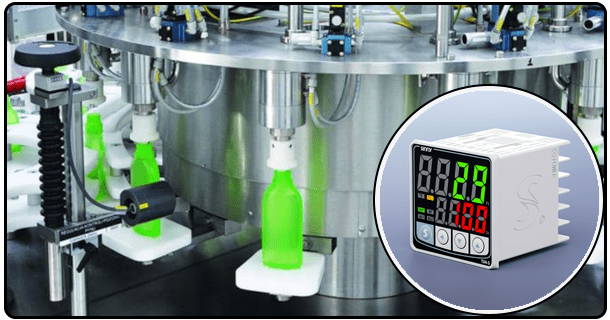
It is important to gather all the necessary components before installing and configuring a PID controller. Core hardware includes the PID unit, which is the brain of the entire system. It processes sensor inputs and generates output signals. The choice of a suitable temperature sensor, such as thermocouples or Resistance Temperature Detectors(RTDs), is crucial. Each has specific properties and operating ranges. The choice will be determined by the application. A load device, which is a component or system requiring temperature regulation (such as a cooling coil or heating element) must also be included. To ensure accurate and secure electrical connections, it is necessary to use reliable power supplies that are compatible with both the controller and sensor. According to the controller's model, a smartphone or computer may be required for configuration and tuning using dedicated software. All these items are readily available to streamline the installation process.
2. Understanding PID Parameters
The PID controller is based on three basic control parameters: proportional (P), integral (I), derivative (D). The key to tuning and configuring the controller effectively is understanding the concepts of these three parameters. This term directly affects the output of the controller in response to current errors - that is, the difference between desired setpoint temperatures and actual measured temperatures. An increased proportional gain can lead to a faster response. However, it may also cause instability or oscillation. The integral term (I), which addresses cumulative effects of previous errors by continuously adjusting output over time to eliminate steady state errors and improve long-term accuracy, is used. A too-strong integral can cause instability. The derivative term (D), which forecasts errors in the future based on changes to the error rate, helps to reduce oscillations, and provides a faster response time to sudden system changes. It is important to understand how these terms work together in order to achieve the balance desired between accuracy, responsiveness and stability.
Guide for Setting up a PID Thermostat
Install Hardware
Initial phase is the installation of all components. Start by mounting the PID unit securely in an accessible and suitable locati0n. Then, you will need to connect the heat or cool element (the load) to the output terminals of the PID control. During this step, it is important to check all wiring against the manual of the controller to avoid incorrect wiring that could cause equipment damage or malfunction.
Charge Up the System
After the installation of the hardware is completed, power up the system. Connect any sensors and load drivers associated with the PID to the respective power supply. Ensure that the voltage and power type of the source (AC/DC), match those specified in the manual. In order to perform initial system tests, it is best to disconnect the power to the device being controlled. This allows you to conduct the checks while the controllable device remains unpowered. Check that the controller is powered on properly and displays the ready or initial state according to its design. It is important to confirm the hardware's basic functionality, before proceeding with software configuration or sensor testing.
3. Connecting to Control Interface
Modern PID controllers are usually operated in conjunction with smartphone applications or computer software, which allows for easier configuration, monitoring and tuning. Connect the PID Controller to the computer or smartphone via the communication interface provided. This is usually done using USB, Ethernet or wireless protocols such as Wi-Fi and Bluetooth. Install the necessary drivers and applications provided by controller manufacturers. Start the software to establish the connection with your PID controller. The graphical user interface is created through this step, which will translate all setup and control operations into an actual control experience.
4. How to configure the PID controller
The software configuration can start once the hardware is powered up and the interface has been connected. Set the temperature target you want to keep in the system. The PID algorithm will try to maintain and achieve this value. Configure the basic parameters of the system in the software. These include the units (e.g. Fahrenheit, Celsius), the sample update time, (the frequency with which the controller calculates output and reads sensor), as well as any output limitations (e.g. maximum output percentage for a heat pump). The calibration procedures are different for each sensor type and manufacturer and should be carefully followed.
5. The PID Parameters
The first step is to configure the settings. To achieve optimal performance, you must carefully tune the parameters P, I and D. Ziegler and Nichols is a common method for tuning the system initially. The Ziegler-Nichols method involves determining first the system's final gain (Ku), and then the ultimate cycling times (Tu), by gradually increasing the proportional gains (P). This is done until the oscillations are consistent in amplitude, at a constant frequency. The empirical formulas and these values can be used to determine the initial value of P, I, D. Some controllers have auto-tuning functions that will attempt to do this automatically. No matter where you start, it is important to fine tune. It involves fine-tuning the gains for P, I and D incrementally. This is often done using trend graphics within the software to show how the system responds to changes in setpoints or disturbances. It is important to have a stable response (minimal fluctuation), one that responds rapidly to changes and maintains the setpoint. It is often a case of trial and error, observing carefully the behaviour of the system before making tiny adjustments.
6. Test the system
It is important to test the controller under real-world conditions after achieving an acceptable tuning. You can run a controlled testing cycle by changing the setpoint rapidly or adding a disturbance known to you (such as temporarily turning off heat sources). Use the data-logging and graphic display functions of the software to monitor the response. Watch key indicators like rise time, settling time and overshoot. Look for signs of excessive oscillation or instability. Re-tune the system if necessary. Test the system until it shows reliable temperature control.
7. Maintenance of the system
Safety must be a priority during the installation, testing and operation of any PID system. When connecting wiring and power components, always follow the electrical safety protocol. Ensure that all connections are secure and properly insulated in order to avoid electrical shock or short circuits. Be careful of possible burns and scalds when working around heating or cooling components. Allow the equipment to sufficiently cool before completing maintenance. Understanding the emergency shutdown procedures of your system and ensuring that all emergency shutoffs are accessible is important. If hazardous substances are involved in the process, you must adhere to all safety protocol and containment measures. Do not modify the system or controller in a way that isn't explicitly suggested by the manufacturer, without assessing the risks. Safety is the first priority. It protects the personnel, the equipment and the integrity the process that you are controlling.
The installation of a PID controller requires careful hardware configuration, software setup, and parameter tuning. This guide will help users create a temperature control loop that is tailored to the needs of their application. To achieve optimal performance however, tuning is key and maintenance must be performed regularly. The process can be tedious and may take several iterations, especially during the calibration phase. However, once the temperature is stabilized and precise, this control will prove invaluable. The ability to set up and tune a PID control ensures a reliable system, but it also provides a foundational skill that is useful for those involved with thermal management and process control. This opens the door for future exploration and optimization. The best results will come from experimentation guided by observations and systematic adjustments.
- Article about Temperature Control with a PID Controller
- Super-precise temperature control adjustment