


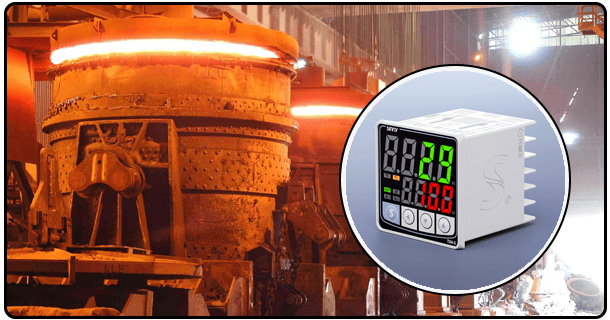
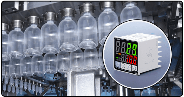
PID Controller Temperature Sensor
I. I. Introduction
Before the advent of sophisticated control algorithms like PID (Proportional-Integral-Derivative), simpler methods were commonly employed for temperature regulation. The most simple is an on-off system that turns on the heater when temperature drops below a threshold, and shuts it down when threshold is met. This method is simple, but it can result in large temperature variations, which oscillate repeatedly around the presetpoint. The system is unable to differentiate between temperature changes and errors of varying magnitudes. It only responds if the temperature crosses a set boundary. A slightly more sophisticated method is a proportional control whereby the rate of heating is changed in relation to the temperature deviation from the target. This method is prone to steady-state errors, which means that the temperature reached at the end of the process may be slightly below the setpoint. The heater must run constantly to make up for this error. The simpler approaches lack finesse and stability for applications that require tight temperature control.
C. C. Introduction to closed loop control: A robust strategy for PID control
PID control emerged as an effective and sophisticated solution for temperature regulation. The PID controller is a keystone in modern process control and it's used across many industries because of its flexibility and robustness. The closed-loop system is the basis of its operation. This involves continuously measuring the actual process variable--in this context, the temperature--comparing it to the desired setpoint temperature, calculating the error between the two, and then generating an output signal that acts on an actuator to minimize this error. PID's "Proportional", "Integral" and "Derivatives" work together to accomplish this, and provide a control level that is far superior than simpler methods such as on-off. PID is the best choice when applications require high levels of accuracy, stability and responsiveness.
D. The Temperature sensor: the fundamental input to accurate PID Control
The temperature sensor is a crucial component of the PID controller. The sensor is the basic sensory element that provides the real-time data required by the controller. The sensor's primary function is to convert the physical property of thermal energy--temperature--into an electrical signal that can be measured and processed by the control system. The current PV is represented by this electrical signal. It can be in the form of a voltage variation, resistance change, frequency or digital value. The PID controller will be unable to make calculations without an accurate temperature sensor. Quality, accuracy and stability are directly related to the effectiveness and performance of the PID system. Selecting the right temperature sensor, and making sure it is correctly integrated are crucial steps to a successful PID temperature control system.
E. The purpose of this article is to explain the relationship between temperature sensors and PID controllers for an effective thermal management.
This article's primary goal is to explore the relationship between temperature sensors and PID controllers. Our goal is to explain why temperature sensors are essential for PID controls and how they work together. This article will explain the fundamental principles of PID, including the P, I and D terms. The article will examine the various temperature sensors that are commonly used with PID control systems and discuss their advantages and limitations. The article also explores the practicalities of integrating temperature sensors with PID controllers, including signal conditioning, communications protocols, and calculation of Process Variables (PV). Understanding this synergy will help readers gain a better understanding of the complex control strategies used in thermal management systems. They'll also be more prepared to design, install, and troubleshoot these systems.
II. Understanding PID Control for Temperature Regulation
PID is based on the idea of a control feedback loop. The loop is made up of interconnected components that work together to keep the process variable, in this case temperature, at a setpoint. The basic structure includes the following: 1) Sensor: Measures current temperature, or PV (Process Variable), and converts that into an electric signal. Setpoint: It is the target or desired temperature as defined by users or processes. Controller: It is the actual PID algorithm, which can be implemented in a dedicated industrial controller or microcontroller. The controller receives the sensor measurements (PV), compares them to the Setpoints (SP), calculates error (E = SPD - PV), then determines a control signal that is appropriate based on PID terms. Actuator: Upon receiving the signal from the controller, this component translates the command into physical actions that will affect the process variable. The actuator in a temperature-control system is usually a heating component (like resistors or heating blocks) that is controlled by adjusting the power, or cooling element. This output then affects the temperature that is being measured by the sensors. The closed loop - Sensor measures -> Calculated error -> Controller calculates -> Actuator reacts -> Temperature Changes -> Measured again by the sensor - forms a continuous, self-correcting cycle.
1. Proportional: Responding to current error (difference in Setpoint and Process Variable).
This term produces a control result that is directly proportional with the error currently between Setpoint (SP), and Process Variables (PV). It can be expressed mathematically as P_output=Kp*E, where Kp represents the proportional gain constant. The proportional term is the system's reaction when it detects how far off the setpoint the temperature currently is. The control signal is stronger when the error is larger. This signals a more aggressive attempt to bring the temperature closer to the desired set point. If the temperature of the room is lower than desired, the output will be large, and more heating may be required. In contrast, when the temperature nears the desired setpoint, proportional output is small. Although proportional control is a necessary and initial response, it can lead to steady-state errors. The system may settle away from its exact setpoint over time because of the insufficient control effort.
Fu Zhi Dai Ma 2. **Integral ):** Eliminating constant-state errors over time. The Integral concept addresses steady-state errors that may be left uncorrected by the proportional. This is done by adding up the errors over time, and then taking a correction based on that value. It's mathematically represented by I_output = E dt * Ki, where E dt is the integral error of time. The integral term adds to the output of the controller as long as there is an error, no matter how small. The constant addition makes the actuator make continuous adjustments (e.g. slightly increasing the heating), until the error has been eliminated. It is useful to compensate for drifts and disturbances over a long period of time that the proportional terms may not be able to overcome. If the integral term becomes too large, this can cause oscillations and instability, particularly if there is a rapid change in the error. 3. **Derivative(D ):** Anticipating errors in the future based on rate of change. The derivative term is a component that predicts the action. The derivative term calculates rate of error change (dE/dt), and then uses that information to predict future errors. It's mathematically represented by D_output = dE/dt * Kd, where Kd represents the derivative gain constant. It dampens the response of the system, particularly when error changes rapidly. The derivative output will be negative if the temperature increases rapidly and the system is on the verge of overshooting the setpoint. This helps to stop the overshoot. In the opposite case, if temperature rapidly decreases, derivative will produce a positive result, which encourages heating to return more quickly. This predictory action improves the response time, stabilizes the system and reduces overshoots and undershoots. The derivative gain must be tuned carefully, since too much derivative can cause noise to enter the control signal.
C. The PID improves temperature control: Accuracy, stability and a faster response time compared with basic methods.
The PID controller offers many advantages to other temperature control methods, such as on-off and basic proportional controls, especially when accuracy, responsiveness, and stability are important. Combining the terms P, I and D allows for the controller to respond appropriately to the current temperatures, to correct previous mistakes through integration and to predict the future trends using differentiation. The synergy has several benefits.
First, increased accuracy can be achieved by the integral term. It eliminates errors in steady state that are often left unaddressed with simpler methods. The derivative term dampens oscillations, preventing overshoot, and improves stability, especially in situations of load or disturbance changes. quicker response times are often possible, because the controller is able to make aggressive corrections (higher P gain), while maintaining stability (D-term). The PID system is also robust and can be used in a wide range of conditions. This makes it ideal for processes that are dynamic, where heating needs may change. PID is the preferred control for applications that require precision and reliability.
D. Parameters important: Error (output), Setpoint, Variable Process (PV),
It is important to understand the terms used in the PID loop control system if you want to fully grasp how it works. Primary parameters include:
·Setpoint: The setpoint is the temperature that the system aims at maintaining. This is the fixed temperature set by an operator or a process logic.
·Process variable (PV),: This is the measured temperature obtained by the temperature sensor. The PID controller continuously monitors the value of the input.
·Error: The fundamental quantity is calculated by the controller. The error (E) is the difference between Setpoint and Process Variable. Positive error shows that the temperature actually is lower than the setpoint. Negative error is the opposite. Zero error is the same.
·Output Controller: The signal is generated using the PID algorithm based on calculated error, P, I and D terms. The output signal will be sent to the actuator. This output's nature (voltage or current) is dependent on how the controller and actuator are configured. This output is often a duty cycle in Arduino systems that use PWM.
III. What is the critical role of temperature sensors?
A. The function of the thermal sensor is to convert thermal energy (temperature) into an electrical signal that can be used. )
Any temperature sensor's primary function is to convert the physical thermal property of its surrounding into an electrical signal. The conversion can be done in a variety of ways. RTDs and Thermistors, for example, produce resistance changes that can be measured with a Wheatstone Bridge. Some sensors produce a variable voltage that changes with temperature. Depending on the temperature, certain sensors like thermocouples produce a voltage at the junction between two metals. Some digital sensors output a signal of frequency (e.g. some RTDs or DS18B20), while others provide a word in digital format that represents the temperature. This thermal data cannot be used directly by the PID controller. It requires an electrical output, which it then processes (e.g. via ADCs for analog sensors), to get a numeric value (the PV) representing temperature.
B. The importance of accurate measurement: direct impact on performance PID (PID calculations depend on exact input ).
Temperature sensors have an impact on overall system performance. The PID algorithm is based on PV to determine error and then calculate E = SP – PV. Any noise or inaccuracy introduced by the temperature sensor will be amplified. The PID controller will make the wrong adjustments if the sensor consistently reports a slightly higher or lower reading. This results in a system that is controlled well away from its desired Setpoint. Response Time, or how quickly the sensor reacts to temperature changes, also plays a part. It is possible that a slow sensor will not give the PID controllers necessary feedback to manage processes with rapid changes. It is therefore crucial to select a sensor that has the right accuracy, response, and resolution characteristics. This will allow you to achieve accurate and reliable temperature control with PID.
C. Temperature control: Sensor accuracy and resolution requirements
Temperature sensors can be classified by their Accuracy which shows how closely the reading of the sensor matches the temperature. Resolution describes the small temperature changes that the sensor is able to distinguish. Both accuracy and resolution play a role in reliable PID temperature control. This is especially true for applications that require tight tolerance. Accuracy requirements are highly dependent on specific applications. As an example, the accuracy required to control the temperature on a 3D Printer Hotend could be as low as +-1degC while the accuracy needed to maintain the temperature in an incubator may only need +-0.5degC. The resolution of a sensor is often expressed in bits. For example, if the sensor outputs 1024 discrete values, the resolution will be 10-bits. A higher resolution will provide a finer level of control but must be coupled with a controller that can handle the added precision. To ensure that the PID system works effectively, the sensor specifications chosen must match the requirements of the task.
D. Selecting a sensor: temperature range, accuracy and response time. Cost, environmental conditions. Interface requirements.
When selecting the right temperature sensor, it is important to consider several factors.
1.Temperature range: Sensor must be able to measure within the operational temperature limit of the application. A sensor that is over-ranged can result in permanent damage.
2.Resolution and Accuracy: As previously discussed, the precision of the sensor must meet the needs of the application. Also, calibration considerations must be taken into account.
3.Response time: Sensors should respond quickly to feedback, allowing them to keep pace with the rate of heating/cooling. A slow response may hinder the performance of PID.
4.Price: Budget restrictions often affect the decision, as they balance performance and price.
5.Environment Conditions: Sensors must meet the requirements of their operating environments (e.g. humidity, vibration, sunlight in direct sun). Certain sensors are stronger than others.
6.Interface requirements: Sensor output signals (analog voltage/current or digital serial communication), must be compatible (e.g. Arduino ADC's for analog sensors and software libraries for digital sensor) with controllers. This section describes the most common types of sensors, along with their characteristics.
E. Sensor Interface: If required by sensor types or controllers, signal conditioning is performed (amplification and filtering of signals, Cold Junction Compensation, CJC).
It may be necessary to process the sensor signals before they are read by the controller. This will ensure that the measurements made are accurate. This process is called Signal Conditioning. This could involve using an operational amplifier circuit to boost the voltage of analog sensors such as many RTDs and some semiconductor sensors or using capacitors to filter noise. Digital sensors require less processing but can involve specific protocols for communication (e.g. One-Wire or I2C/SPI) that need to be supported both by the controller as well as appropriate libraries. Cold Junction Compensation is a critical example. It's essential for accurate thermocouple measurement. CJC is required because thermocouples are designed to measure the difference between a measuring junction and reference junction. The reference junction is often not constant. The temperature of the measuring junction is measured (often with a separate sensor), and a correction factor applied to the thermocouple measurement. The importance of knowing sensor specs and making necessary modifications is highlighted in this topic.
F. Common Temperature Sensing Technologies for PID Control: Thermocouple Amplifiers, Digital Thermometers, Humidity sensors (e.g. DHT11/22), and digital thermometers.
In conjunction with PID control systems, several sensor technologies are used. They each have their own strengths, and are suitable for different application.
1.Thermocouples Used widely for their excellent temperature range, from cryogenic temperatures to extremely high temperatures. Measures the difference in temperature between two points. For accurate readings, a sensor like the MAX6675 is required (which provides cold junction compensation and digital output).
2.RTDs: RTDs are highly accurate and stable over a large temperature range. The resistance changes proportionally to the temperature. They require a bridge and an ADC (or dedicated amplifier IC) for example, MAX31865. There are also digital RTDs, which simplify the interface.
3.Thermal sensors: Thermal sensors are very popular because of their low price and high sensitivities.