


Pid digital 12V DC temperature controller
1. pid temperature controller
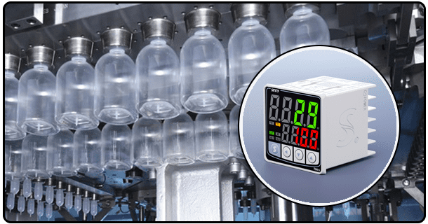
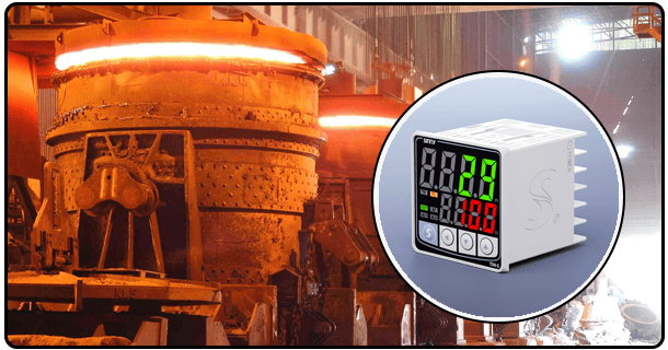
This article focuses on the 12V DC version, which is suitable for a wide range of portable applications.
2. Understanding PID Control
The PID algorithm is at the core of the 12V DC PID Temperature Controller. It's a mathematical model that minimizes the difference between the desired setpoint (or target) and the actual variable. PID stands for proportional, integral, and derivative, which are three terms interconnected yet distinct that make up the control law. Understanding these three components will help you to understand the PID controller's effectiveness in temperature control tasks.
Control (P) by Proportional: This term produces an output signal directly proportional the error. The difference between the setpoint temperature desired and the temperature actually measured is called the current temperature. A larger error results in a stronger control signal. The P-control provides an immediate response but leaves behind a steady state error. This means that the temperature may not reach the desired set point and could drift. This response is determined by the 'proportional gains' (Kp). A higher Kp will result in a quicker reaction, but also more oscillation.
Integral Control (I): This term is used to address the error at steady state inherent in P-control. The integral term calculates the sum over time of all past errors and produces an output which continuously corrects for this discrepancy. If the error continues, it will grow the integral term, which in turn, changes the output of the controller until the problem is fixed. The integral winding-up can cause a delay in the control output, causing the controller to overreact.
3. Components for a PID temperature controller 12V DC
Each component plays a crucial role during the temperature measurement, processing and control phases. Understanding these components is crucial for design as well as troubleshooting.
The most common types of sensors used in PID controllers that run on 12V DC include:
Thermocouples They are robust, have a wide temperature range, and relatively low cost, although they suffer from slow response times, non-linear output, and a slower rate of heat transfer. K, T, and J types are commonly used.
Resistance Temperature Detectors: Provide higher accuracy and more stability over a smaller temperature range than thermocouples. The output is linear, which simplifies signal processing. The most common RTDs are platinum (Pt100 and Pt1000).
Thermistors Offer excellent sensitivity, fast response time, and are suitable for applications that require rapid temperature detection. Examples include cooling systems, electronic devices, or other similar situations. Their temperature range, however, is usually more restricted than that of thermocouples and RTDs. The sensor then converts this physical temperature change to an electrical signal, such as a voltage change or resistance, before transmitting it to the controller.
Control Unit: The brain of the device, it processes the signal input from the sensor to generate the output signal for the actuator. Modern systems often use a PID Integrated Circuit or a Microcontroller. The controller compares the reading of the sensor (process variable), with the setpoint temperature. The controller determines corrective actions based on the comparison, the PID terms calculated, and the I and D values. Microcontrollers are flexible, programmable, and can incorporate extra features such as communication interfaces, or user interfaces. PID integrated circuits are a simpler and more efficient solution. They're designed to implement the PID algorithm.
Power supply: 12V DC specifies the voltage required for the controller and other possible components such as the sensor signal conditioning circuitry, or the user interface. For consistent performance, a stable 12V DC supply must be used. Depending on cost and efficiency, switching power supply or linear regulators can be chosen. Power supplies convert incoming voltages (from a wall-adapter or battery, for example) into the 12V DC required by controllers.
Actuators Output: These components implement control actions determined by the controller. They can either remove or add heat to the system (or do both), to get the temperature measured closer to the setpoint. The following actuators are commonly used in systems that operate on 12V DC:
4. It Works
A 12V DC temperature controller uses a cycle that includes measurement, comparisons, calculations, and actions. This is called a closed loop control system. The dynamic nature of this process allows the temperature to closely follow the setpoint even when conditions change or loads are disturbed. This cycle is essential to understanding the controller.
Measurement of Temperature: This process starts with the sensor that is installed in the system or environment whose temperature must be controlled. Sensor continuously converts the physical quantity (e.g. voltage change or resistance) into an electrical signal. The signal can be conditioned (e.g. amplified or linearized), before it is sent to the control unit.
Acquisition of Signals and Comparison: Upon receipt of the sensor's signal, the controller (typically a PID IC or microcontroller) converts the signal to a digital or a processed-analog value that represents the current temperature. The controller unit compares the measured temperature (the Process Variable, or PV), with the setpoint temperature that was defined by the user. error is calculated by dividing SP by PV. The PID algorithm is driven by this error.
Execution of the PID Algorithm: When the controller calculates the control output (u) using the error signal E, it applies the PID algorithms. The calculation takes into account the current error (Proportional), the history of errors in the past (Integral), and rate of change (Derivative) simultaneously. This mathematical formula typically looks something like:
Output (u) = Kp * E + Ki * E dt + Kd * dE/dt
These are Proportional Gains, Integral Gains, and Derived gains. These gains have a significant impact on the behaviour of the controller. These calculations are performed by the controller's software or hardware based on programmed gains, and current error values.
Generation of Output Signal: After the result from the PID calculations (the output control u), the signal is translated to a format that can be used by the actuator. The output signal represents typically the level of cooling or heating effort desired. A higher output signal could, for example, correspond to greater power sent to the heating element or higher speeds of a cooling fan.
Control of Actuator: A controller transmits an output signal (e.g. via digital pins, analog voltage, or PWM signals) to the actuator. This signal is received by the actuator, which then performs any physical actions required. The actuator increases heating or decreases cooling if the temperature measured is lower than the setpoint. The actuator decreases heating or increases cooling if the temperature measured is higher than the setpoint. The actuator may only take minimal action if the temperature is near the setpoint.
Loop closure and feedback: Through the temperature sensor, the controller monitors continuously the output from the actuator as well as its impact on system temperature. The feedback loop allows for dynamic system response. The error changes if disturbances happen (e.g. a change in load or a drop in temperature caused by a door being opened). This will trigger a calculation using the PID algorithm on the following cycle. The continuous sequence of measurement, comparison and calculation is used to ensure that the setpoint temperature remains as close to it as possible. This shows the closed-loop control.
PID temperature controllers are able to provide highly accurate and reliable temperature regulation by adapting their dynamic system dynamics.
5. Design and construction
A 12V DC temperature controller that is designed to be robust and reliable relies on not just a solid understanding of control theory, but also on the design. In this phase, the requirements are translated into an electronic system that is reliable, efficient, and adheres to safety standards.
Schematics and Circuit Design: Create detailed schematics that show the connection between components. The power supply (designing a 12V DC regulator stage) is followed by the sensor interface (considering signal conditions like amplification and linearization for thermocouples), core PID logic (using a dedicated IC or microcontroller), and output driver (using transistors or solid state relays to switch a 12V load). This design should ensure that the signal is processed accurately, there's adequate power delivered, and it protects against spikes in voltage or wrong wiring.
Component selection: Selecting the correct components is crucial for performance and durability. The selection criteria are:
- This detailed overview of the 4 channel PID temperature controller will give you a better understanding
- Theoretical Control of Temperature Using PID Controller Theory