


Setting Up a PID Temperature Controller for Precise Control
1. Introduction: Understanding PID Temperature Control

In many applications - from scientific experiments, to industrial processes that require precision temperature control and everyday products like incubators and 3D printers - the ability to regulate temperatures precisely is essential. To achieve and maintain a precise temperature, a sophisticated system is required. Among the most effective methodologies available, PID (Proportional-Integral-Derivative) control stands out. The PID algorithm is implemented in a controller unit that allows for a tighter temperature regulation by manipulating the heating and cooling elements. A PID controller constantly calculates the temperature difference between the setpoint and actual temperature. It then changes the output power to the actuator. Its three parts, Proportional Integral and Derivative work together to optimize this temperature error. Anyone who wants to automate temperature in a reliable way must know how to set up and calibrate a PID controller. This guide walks you through all the steps necessary to establish a PID system that is functional. It covers component selection, installation, configuration and tuning.
2. The Core Components
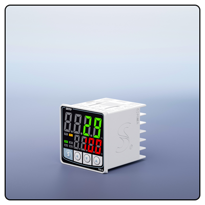
The success of a PID system relies upon the Xie Tong, or synergy (of several components). Every component plays an important role in ensuring the system works properly. The PID controller is the central brain for the system. The modern controller ranges from basic analog units with knobs and screens to digital devices that offer programmable functions, USB and Ethernet connectivity, and graphic interfaces. The controller, regardless of its type, receives the temperature data and processes it with the PID algorithm to generate an output signal. The output is usually a Solid State Relay or a Relay that physically turns on/off the power. It can also be an analog voltage or a Solid State Relay. The actuator, or heating/cooling element is what the controller controls. Electric heating strips, Peltier Modules (also called thermoelectric coolers), forced air fans, and solenoid vales controlling hot or cold liquid are all examples. It is important to select an actuator that has the right power rating and operating characteristics for your system. The first step to a successful PID configuration is understanding the functions and interactions of the core components.
3. Preparation Before Physical Installation
To ensure safety and efficiency and to make the setup easier, all preparations are done meticulously before starting with physical assembly. When dealing with temperature control and electrical systems, safety must be a priority. Start by understanding both the power needs of the controller and actuator. Check that your power supply voltage, current and capacity matches the specs in both the manuals of the actuator and controller. Proper grounding of electrical equipment is also crucial to ensure safe operation and prevent damage. Consult the relevant safety guidelines and standards applicable to your area and application. Create a complete list of the materials and tools you will need. The PID controller, chosen temperature sensor and heating/cooling actuator are typically included. Also, any cables required (power cables and sensor wires as well as output control cables), all connectors and specific installation tools such a screwdriver, wire strippers and pliers. It is important to have everything ready before the installation begins. This will prevent delays and errors. It is important to understand the application's requirements. Consider the specific temperature range to be maintained and the characteristics of your load. How quickly should the temperature change? What is the process' sensitivity to small fluctuations? What is the thermal inertia? These questions help anticipate potential problems and select appropriate tuning strategies.
4. Installing the Physical System and Wiring
The next step is to install the components. Start by choosing a suitable locati0n for mounting the PID control. The controller should be accessible to monitor and adjust, but protected from dust, moisture and extreme temperature changes that may affect the readings or operation. Use the mounting hardware that comes with the controller. Connect the temperature sensor once it is mounted. Connect the sensor to the input terminals of the controller according to manufacturer instructions. Install the sensor simultaneously in its ideal locati0n. In many cases, it is necessary to place the sensor in contact or close to an object or medium that needs temperature regulation. This will ensure it accurately represents the temperature in the desired zone. To prevent short-circuits or accidental disconnections, the connection should be insulated and secure. Connect the output terminals of the controller to the actuator's (heating/cooling element). The output capability of the controller (relays or SSRs) will determine what type of connection you use. The actuator requirements. Assure that all electrical safety protocol are followed when connecting the actuator to its power supply. Where applicable, pay close attention to the polarity. Verify all connections after completing them. Check each wire with the wiring diagram in the manual for the actuator and controller to ensure that it is securely connected. Check for loose wires, exposed conductors or the wrong polarity. Connect the power supply to the controller once you are satisfied that the wiring is in good condition. During this initial configuration and testing, the controller should be powered up.
5. Initial configuration in the controller software/interface
The first step in the setup process is the software interface or controller. Once the installation has been completed and the system turned on, (the actuator may initially have to be unplugged for safety reasons during the configuration), you can begin the actual initial set-up. Modern PID controllers have intuitive menus and a graphic display, while older analog controllers may require manual adjustment. Set the basic parameters first. Decide whether you want to use Fahrenheit or Celsius as your temperature units. The controller must then identify which type of sensor is connected. This can be selected via a menu, for example, "Thermocouple Type K" or "RTD Pt100". It is important to correctly identify the sensor type for the controller so that it can interpret sensor signals. After completing these settings, enter the target temperature into the controller. The system will aim to maintain this temperature once the tuning process is completed. After saving the setting, you can make initial observations by watching the display of the controller as it processes the sensor input. The system may attempt to reach its setpoint. This is a good indication that it's working. The PID parameter tuning is the next step.
- How to implement a software-based PID temperature controller
- A Guide to the Schematic Diagram of PID Temperature Control