The Proportional-Integral-Derivative (PID) Controller: A Comprehensive Overview
I. I. Introduction: Need for Control in Dynamic Systems
Automated control and automation systems play a vital role in the operation and management of many modern industrial devices. They enable precise and efficient dynamic system operations. The ability to control a system to achieve a specific state, whether it's the tiny microelectronics of a smartphone or the huge HVAC systems found in factories and aircrafts is essential. This regulation can be difficult to achieve due external disturbances or the non-linearity inherent in many processes. The Proportional-Integral-Derivative, commonly known as PID, controller emerges as a foundational and remarkably versatile solution to this fundamental problem in control engineering. A PID controller is a mechanism which compares an desired setpoint with the measured value of a process variable. It then calculates and minimizes this error. The simplicity of the PID controller makes it a versatile tool that can be used in a wide range of situations.
II. Core Concept: Proportional-Integral-Derivative Control
The PID controller is based on an easy-to-understand but powerful principle. The PID controller works by measuring continuously a PV (process variable) with a sensor. The measured value is compared with a setpoint (SP) that represents the desired value or state for the process. This difference is called the error (E = PV - SP). This core logic calculates an output to correct the error. The computation is a summation of three mathematical terms that are distinct but connected, with each term contributing to the control action in a unique way: the Proportional term (P), the Integral term (I) and the Derived term (D). In most cases, the output of a PID controller can be expressed using the following formula: Output = E + Ki * E/dt + Kd * dE/dt. Kp, Ki and Kd represent the gains associated with each component. It is important to understand how these terms work in order to fully comprehend the PID controller.
"
" III. The three modes explained (detailed breakdown)
Effectiveness of PID controllers depends on their ability to function and tune its modes. The three modes of a PID controller each address different aspects over time and when combined, they provide robust control.
It is the Proportional mode that forms the base of the PID Controller. The controller output depends directly on the value of the current error. The proportional gain (Kp) is determined by multiplying current error (E). A larger error will result in a proportionally bigger output signal and a lower error, a smaller one. P is primarily used to respond immediately to an error. The system tries to correct any deviations as soon as possible. Value of Kp determines the magnitude of response. Kp values above 0 indicate a fast reaction time to an error. Increased Kp can also increase the sensitivity of the system, and this may manifest itself as oscillations or overshoots (the system exceeding the setpoint). A low Kp result in a slower response and a larger error. The presence of steady state error is a significant disadvantage associated with only proportional control. Even with non-zero errors, the system will not always reach the setpoint. It may stabilize slightly off the target. The P-term offers an initial corrective action, but it is often dependent on the assistance of the other modes in order to remove this persisting error.
B. B.
The Integral mode can be used to address the error at steady state inherent with proportional control. I is a term that focuses on the sum over time of all errors, integrating past history. Calculate the integral term by multiplying integral gain (Ki), by the cumulative error (often expressed as E dt). The integral term grows progressively when the error persists for an extended period of time, no matter how small. The integral term grows to increase the output of the controller, forcing the system to adjust and eventually eliminate the steady state error. This I-term pushes the variable toward the setpoint, and ensures convergence. The addition of an integral term has some potential downsides. The integral term may slow the response time of the entire system. If the error is changing direction often (such as oscillations), it can accumulate in one direction, then decrease rapidly when the error reverts. The back and forth accumulation of the integral term and its reversal may cause oscillations and overshoot in a system, which is sometimes called 'integral windsup'. To maximize the ability of the integral term to eliminate errors, it is important that the Ki gain be tuned carefully.
C. Derivative (D) Mode:
The derivative mode adds a component of forward-looking control to the action. The D-term anticipates errors in the future based on how fast the error changes. The D term calculates its own contribution by multiplying derivative gain (Kd), by rate of error change (dE/dt). If the error increases rapidly, then the derivative will produce a signal that opposes this change in an attempt to avoid a big overshoot. In the opposite case, if an error decreases rapidly, the derivative will provide a signal to help settle the system. D-term benefits include increased stability, decreased overshoot and improved damping of oscillations. The D term acts as a smoother, reducing rapid fluctuations. It also prevents the system from overreacting to noise or short-term disturbances. The D-term helps achieve a stable, controlled response by anticipating the tendency of the system to oscillate or overshoot. The derivative term, however, is very sensitive to the noise in sensor measurements. The derivative gain can amplify rapid changes or noise at high frequencies in the signal measurement, which could lead to unstable or erratic control. The D-term is most useful when combined with P and I terms. Its gain (Kd), which must be adjusted carefully, can often be smaller than Kp or Ki.
IV. How PID controllers work: the control loop
It is easiest to understand the operation of PID controls within the context of a feedback loop. The closed loop is a system in which the controller constantly monitors and adjusts the process based on observations. These steps are both sequential and circular:
Measurement Continuously measures the state of the process using a sensor that is selected according to the measurement variable (temperature, pressure, flow rate or position) and for the particular application. The Process Variable is this measured value.
Comparison Compares Process Variable with Setpoint. Setpoint is the value of the variable or the condition that the controller wants to achieve.
Calculation of Error: Difference between Setpoint and Process Variable. The Error value (E = PV - SP) quantifies the current deviation of the process from its desired state.
Calculation of Control: In the PID controller, the algorithm calculates the corrective action by analyzing the current error, and, when active, the historical errors (for I term), and rate of error change (for D term). The output signal is determined by the I and P terms multiplied by the respective gains of Kp, Ki, and Kd.
Action: A calculated output from the Controller is sent to a Actuator. Actuator is designed to influence the process variables by manipulating the input. For example, you can adjust the valve position, change the power to the heater or motor or alter the fluid flow.
Process Variable Change: By changing the Process Variable, the actuator modifies the Process.
Repetition: The steps 1 to 6 are repeatedly repeated (often at a rate of many repetitions per second). The controller continuously monitors, compares and calculates and then acts to reduce the error.
The PID controller's performance and stability in dynamic environments is maintained by this continuous feedback.
V. The Key Components in a PID System
The components of a PID system that work together to form a functional control system are distinct, but they also interdependent.
Transducer/Sensor: The component responsible for determining the process variable to be controlled. It is important to choose the right sensor for your application. For example, thermocouples and resistance temperature detectors are used for measuring temperature. Pressure transmitters measure pressure. Flow meters measure flow. Sensors must be reliable and accurate. They also need to suit the environment in which they are used.
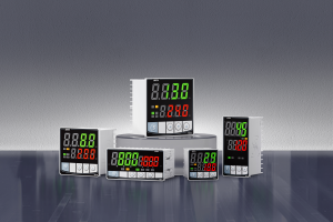
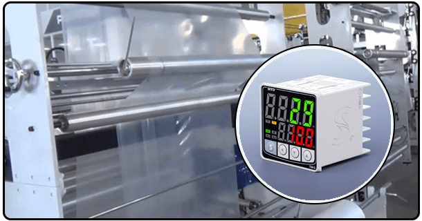
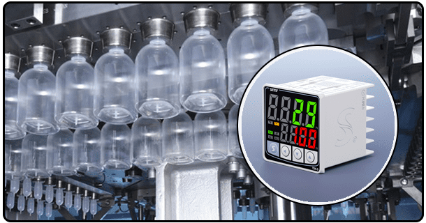
Controller: The controller is responsible for implementing PID algorithms. It can come in many forms. The controller can be a hardware unit, usually part of a Programmable Logic Controller or Distributed Control Systems (DCS), containing circuitry and software modules that are specific to PID control. PID is increasingly implemented by software on microcontrollers or general purpose computers. The controller, regardless of its form, receives a sensor signal and calculates it's error. It then processes the signal according to PID formula.
Actuator An actuator is a device that receives an output signal sent by the controller. It then translates the information into physical actions to manipulate the process. The sensor's role is the opposite of its own - it controls the input to the process. The choice of actuator depends on the type of process to be controlled. Examples include solenoids for on/off switching, electric motors to control position and speed, valves that regulate flow or temperature (depending on the process), heaters or cooling systems (to maintain the desired temperature), as well as variable
- A Guide to Reducing Overshoot on PID Controls
- Temperature Control Using PID Controller: Circuit Diagram & Explanation


