A comprehensive guide to PID temperature controllers and SSRs
1. Introduction
In order to achieve such a level of control sophisticated systems are used. PID Temperature Controllers paired with Solid State Relays are among the most popular and effective solutions. This article gives a detailed overview of PID controllers that are integrated with SSRs. This article begins with defining the core components and explaining their distinct roles, as well as the benefits of combining them. Understanding this technology is important to achieve accurate temperature control. This outline will guide the reader to the next sections. It will help them understand the benefits, the advantages and the applications of PID controllers combined with SSRs.
2. Understanding PID Controllers
A. A. Basics of PID control
PID controls are based on calculating the error value, which is the difference between desired setpoint temperatures and actual temperature measurements. The error value is processed by three different control actions that each contribute to the final output signal.
Control (P) by Proportion: A proportional control produces an output directly proportional with the error. The proportional control will produce a large output change if the temperature has been significantly shifted from the set point. A small mistake results in smaller adjustments to the output. Pure proportional control can reduce error but often results in a steady state error. This means that the system does not reach its exact setpoint, and it may oscillate.
Integral Control (I): This term is used to correct the error at steady state left by the proportional control. The integral term calculates the sum over time of all the errors and then adds or subtracts accordingly from the output. The integral action will increase or decrease the output continuously until the error has been eliminated if the error continues to persist. It can help eliminate offsets but it may also lead to slower responses and in some cases instability or oscillations.
Control (D) Derivative: This derivative term is focused on the rate at which the error changes. The derivative term predicts errors in the future based on current trends and produces an output which opposes that rate of change. The derivative term dampens the overshoot of the temperature if it is quickly deviating away from the setpoint. This increases stability and speed of response, but it is susceptible to noise. It can also be unstable if implemented incorrectly.
PID Equation with Variables
Standard PID equation can express the relationship between the terms (i) and (u), the control output, mathematically.
u(t) = Kp * e(t) + Ki * e(t)dt + Kd * de(t)/dt
Where:
u (t) represents the output control signal at the time .
e(t), calculated by dividing the Process Variable measured (PV) with the Setpoint desired (SP), is an error occurring at the time t.
Kp is the proportional gain, Ki and Kd respectively. They are tuned parameters that are determined by the process to be controlled. These tuning parameters are essential for optimal performance.
is the integral error of time.
de (t)/dt is the derivative of error in relation to time.
B. B. Applications of PID controllers
PID controllers are widely used in many fields due to their versatility and effectiveness. Common applications include
Industrial processes: Control of chemical reactor temperatures, control of boilers, drying and extrusion process, control over material temperature, etc.
Laboratory equipment: Temperature regulation of ovens, control for incubators, calibration and stability of environmental chambers.
Air conditioning and Refrigeration: Maintaining exact temperatures in data centers, food storage facilities, and pharmaceuticals.
Automotive: Engine control systems, antilock brake systems (ABS), climate control.
Home Appliances: Air conditioners (temperature of water), washing machines, refrigerators and other domestic appliances.
C. Benefits of using PID controllers
3. PID temperature controllers have several advantages.
Accuracy and Precision: The PID system can be used to achieve tight temperature control bands. This minimizes deviations of the setpoint.
Stability PID controllers tuned properly can maintain stable performance even when operating under different load conditions.
Flexibility: A system's flexibility can be adjusted to meet changing process requirements or dynamics.
Automation After being set up PID controllers automatically automate temperature control, with minimal intervention from humans.
Fast response: These devices can react quickly to temperature deviations, and return the temperature to its setpoint.
III. Solid State Relays: Introduction
PID controllers make intelligent decisions, but they require a reliable actuator that can execute those decisions. This includes turning on and off heating or cooling systems. Solid State Relays are the ideal solution for modern temperature control. It is important to understand how SSRs work and their benefits over traditional relays in order to appreciate their synergism with PID Controllers.
A. A. Definition and Function
SSRs are electronic switches that turn on or off power using semiconductor devices. They usually do not have mechanical moving parts. SSRs are completely electronic, unlike older mechanical relays that use electromagnetic coils for opening and closing contacts. SSRs are used to control electrical loads such as motors or heating elements using a low power signal from an external device.
B. Comparative Analysis with Mechanical Relays
Since decades, mechanical relays are the most common electrical switch. SSRs have several benefits:
A Longer Operating Life: Because SSRs do not have moving parts that can wear out, they are able to operate for a longer period of time than mechanical relays.
Switching speed: The SSRs are able to switch on and off more rapidly than mechanical relays.
Less Noise: The SSR is quiet, while mechanical relays make clicking noises when they switch.
No Arcing When switching inductive loads with SSRs, the electrical arcs produced by mechanical relay contacts are not destructive or hazardous.
Less Electromagnetic interference (EMI): The electronic switching generates typically less EMI than mechanical contact bounces found in relays.
C. Different types of SSRs
There are different types of SSRs, which can be distinguished mainly by the amount they handle.
DC SSRs Are designed to switch DC loads such as light emitting diodes or motors.
AC SSRs AC SSRs are designed to switch AC loads such as standard light bulbs or heating elements. AC SSRs are further classified based on the zero-crossing switch behaviour.
SSRs with zero-crossing: Change the load when the AC cycle reaches the zero point. These are quieter, generate less electromagnetic interference (EMI), but handle surge currents at a lower level than non-zero crossing types.
SSRs that do not cross zero: Change the load during the AC cycle. These SSRs can handle high surge currents, but they also produce a lot of noise and could increase the electrical dangers.
There are also classifications based on the control input voltage, e.g. low-voltage DC inputs of 3-5V, or internal protection (such as overvoltage protection, undervoltage protection, and short circuit protection).
D. Use of SSRs for Temperature Control
SSRs are a powerful tool for controlling temperature when used in conjunction with PID controllers.
Precision Control: The SSRs are able to respond very quickly to changes in control signals from the PID Controller, which allows for finer adjustments of the power supplied to the heaters or coolers.
Fast response: Due to their electronic nature, they can be switched on and off quickly. This contributes to the speed at which the loop controls the temperature.
Durability: By eliminating mechanical contacts, wear and tear is reduced significantly. This leads to a system that becomes more durable and reliable over time.
Quiet operation: The absence of mechanical noise allows SSRs to be used in applications that require quiet operation.
Compatible with PID: Typically, SSRs accept low voltage DC control signals from standard PID controllers. This makes integration easy.
4. Combining SSRs and PID controllers to control temperature
Integration of PIDs and SSRs provides a flexible, powerful solution for temperature control. The section below explores the way these components interact and key design considerations.
A. SSRs enhance PID control
SSR is the last stage of the control loop. It converts the PID controller's calculated output into the actual energy delivered to the cooling or heating element. PID controller is the brain, determining corrective actions based on differences between setpoints and measured variables. SSR is the "muscle" that executes this action, precisely controlling power flow. This synergy provides highly precise and stable temperature control. SSR's fast switching ability ensures the PID controllers are adjusted quickly. This results in a more responsive control system.
B. B.
The integration of a PID with an SSR requires several steps.
Choosing Components Pick a PID controller that is suitable for your load. (This can be a hardware module, or software on a Microcontroller). Also, choose an SSR with the appropriate rating (heating elements type, power ratings, voltage, current and compatibility of control signals).
Sensor connection: Connect the temperature sensor to the input of the PID controller to measure PV.
Connection for the load: Connecting the heating element or the cooling elements to the output terminals on the SSR.
Signal Control: Connecting the PID's signal output (usually low voltage DC signals like 0-10V or 4-20mA) to SSR control input. Verify that the PID controller's range of output matches the SSR input specifications.
Power supply: Make sure all the components are correctly powered by appropriate sources (PIDs, SSRs, sensors, loads).
C. C. Considerations for System Design
When designing a system, it is important to consider several factors.
Type of load: SSRs must meet the requirements for specific heating elements (such as resistive, inductive etc.). The SSR must be suitable for the specific heating element load (resistive, inductive, etc.).
Compatibility of Control Signals: Input and output types (voltage loop or current circuit) for the SSR must be compatible.
SSR Heat Sinking: SSRs generate heat during operation. It is important to have a heat sink that can withstand high power, and perform reliably. Manufacturer's specs will determine the size and type required.
Tuning the Control Loop: Achieving stable and responsive controls requires tuning Kp, Kd, and Ki gains of PID controllers. It is important to get this right. This can be done by using automated methods or some trial and error.
Safety Use appropriate safety measures such as overtemperature prevention (e.g. a high limit switch attached to the PID or an automatic disconnector).
D. Example PID temperature controllers using SSRs
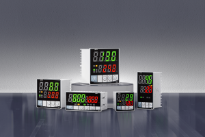
Many commercially-available modules and systems combine PID controllers with SSRs. They are often packaged as complete systems for specific applications.
Industrial temperature controllers: Units designed to withstand harsh conditions, with multiple inputs and outputs (such as Modbus) and large displays.
Laboratory Controls: Small and compact units for the control of ovens, incubators and chambers.
SSR modules: Certain manufacturers offer SSR modules that can be used in conjunction with PID controllers to provide flexibility for system design.
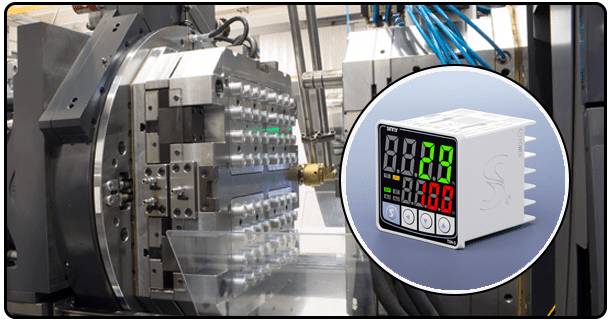
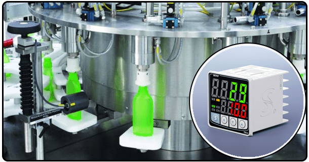
The examples below demonstrate how PID+SSR can be used in a variety of industries, and at different scales.
5. Implementation and operation
To deploy a PID with SSR successfully, careful calibration and monitoring is required. This section is a guide on how to put the system in operation and maintain it.
A. Installing the system
Initial setup includes physical connections and basic configuration.
Mounting : Install the temperature sensor and all associated components, including PID controllers, SSRs, and temperature sensors, according to the manufacturer's instructions.
Wiring: Plug the temperature sensor into the input terminals of the PID. Connect the SSR's output terminals to the SSR load (heating/cooling component). Connect the PID controller output to SSR control input. All wiring must be secure and polarized correctly.
Power connections: Connect power supply for PID controllers, SSRs, sensors, and loads. Check voltages, polarity and connections.
Initial Configuration Access the settings menu of the PID controller via the keypad or computer connected to the system. Basic parameters can be configured:
Temperature Control: Select temperature.
Units : Choose the temperature unit (for example, Celsius or Fahrenheit).
Sensor type: Select the right temperature sensor (e.g. Type K thermocouple or PT100 RTD).
Setpoint Enter desired temperature:
Range of input: Select the range to be used for temperature sensors.
Range of output signals: Select the range and type (e.g. 0-10V) for your output signal.
B. B.
To ensure that the system is operating correctly and efficiently, calibration and tuning are essential steps.
Calibrating: This ensures that the temperature sensor gives accurate readings for the PID controller. It involves calibrating the PID controller by comparing sensor output with a temperature source that is known to be accurate and then adjusting sensor calibration parameters. Please follow the manufacturer's directions for both your sensor and your PID controller.
Tuning: This involves adjusting Kp, Kd, and Ki gains in order to obtain the desired performance of the control: rapid response, minimal undershoot and no steady state error. Tuning methods that are commonly used include:
Ziegler Nichols Method: Heuristic methods that involve finding the ultimate gains (Ku), and the ultimate periods (Tu), of the system. Then, the gains are set based on the empirical formulas.
Manual tuning: Start with conservative gains, and increase them gradually while watching the response of the system to determine a stable setting.
Automatic Tuning: Advanced PID controllers have built-in automatic tuning routines which adjust gains automatically according to the dynamics of the system.
Iteration may be required during the tuning process. It is important to reduce the oscillations of temperature around the setpoint, and make sure the system achieves and maintains that temperature quickly.
C. Monitor and adjust the temperature
After the calibration and tuning, you can put it into use. It may be necessary to monitor the system regularly and make adjustments from time-to-time.
Monitoring: Monitor the performance of the system over time. Monitor for drift and make sure the system reacts to changes in load or disruptions. Most PID controllers have displays that show the temperature at present, as well as setpoint and output levels.
Modifications: The PID gains can be readjusted if the performance of the system degrades, or if the changes to the process demand different control characteristics. If the requirements for the setpoint change, you can simply modify the value of the setpoint in the controller.
D. Safety Considerations
Any temperature control system that uses heating elements must be safe. Safety considerations for temperature control systems include:
High Limit Switch: Install an additional temperature sensor in connection with a high limit switch. The switch will disconnect the power from the heater if the temperature reaches a certain level. This is a failsafe.
Grounded Components: Make sure all electrical components are grounded properly to avoid any hazards.
Insulation : Use suitable insulation on heating elements and wires to avoid accidental burns.
Electrical wiring: Select connectors and wires that are suitable for your load voltage and current. Also, ensure the connections and all other parts of the circuitry is secure in order to avoid overheating and short-circuits.
Compliant: Ensure that the design of your system and its components conform to relevant electrical standards and safety regulations (e.g. CE, UL).
Inspection Regular: Inspect the system periodically for wear or damage. Pay particular attention to the SSR, the heating element and the temperature sensors.
6. Benefits of using PID temperature controllers in conjunction with SSRs
Combining PID and SSR controllers has many benefits. It is a popular solution in temperature control.
A. A.
The PID controllers have a high level of precision and accuracy. The system, when paired with a SSR that offers fine control of power delivery can keep the temperature target very close to setpoints, and often within extremely tight tolerance bands. The level of precision required is critical for any process where changes in temperature can have a significant impact on product quality and reaction rate.
B. B.
When tuned properly, PID controls can maximize the amount of power that is delivered to the heater element. The PID control only applies the power needed to maintain and reach the setpoint. This avoids overheating or energy waste. The SSRs are more efficient because they allow for better control, and may even have lower losses of power compared with mechanical relays that switch high currents. The result is significant energy savings in continuous or large-scale processes.
C. C.
SSRs increase the longevity of the system. SSRs do not have moving parts, unlike mechanical relays that can wear over time from electrical and mechanical stresses. SSRs are resistant to vibration and shock. This, combined with the high reliability of the electronic components used in the PID control system, results in systems with much longer operating lifespans.
D. D. Reduced Maintenance Needs
PID+SSR control systems require less maintenance than older methods of controlling once they are properly calibrated and tuned. SSRs do not have mechanical contacts, which reduces failures due to wear or erosion of the contact. If the conditions of the process remain stable, the intelligence of the PID control minimizes manual adjustments. While it is still recommended to perform regular inspections of the critical components such as heat sinks, sensors and other parts.
- PID Temperature Controller Wiring Diagram 220V: A Detailed Guide
- PID Temperature Controllers Manual: Comprehensive Guide for Operation and Implementation


