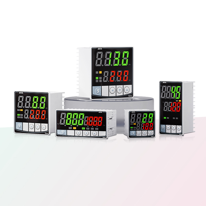
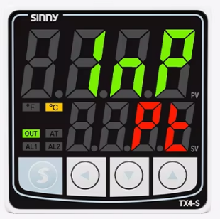
How to connect a temperature controller
Preparations before connection: Lay a solid foundation and avoid mistakes
Equipment compatibility (power parameters/control mode/power) : Ensuring the compatibility of the equipment is directly related to whether the product can operate normally
1. Power supply voltage:
Commonly used voltages include 220v, 12vDC, and 24VDC. 220v- household voltage, 12vDC, and 24VDC are low voltages. The output voltage of the power supply and the rated voltage of the controlled device, according to the voltage marked on the device label. Use within a reasonable range. Do not connect to 380v industrial voltage to avoid equipment burnout and unusability due to voltage mismatch
2. Control mode:
The control mode of the temperature controller must match the interface of the equipment.
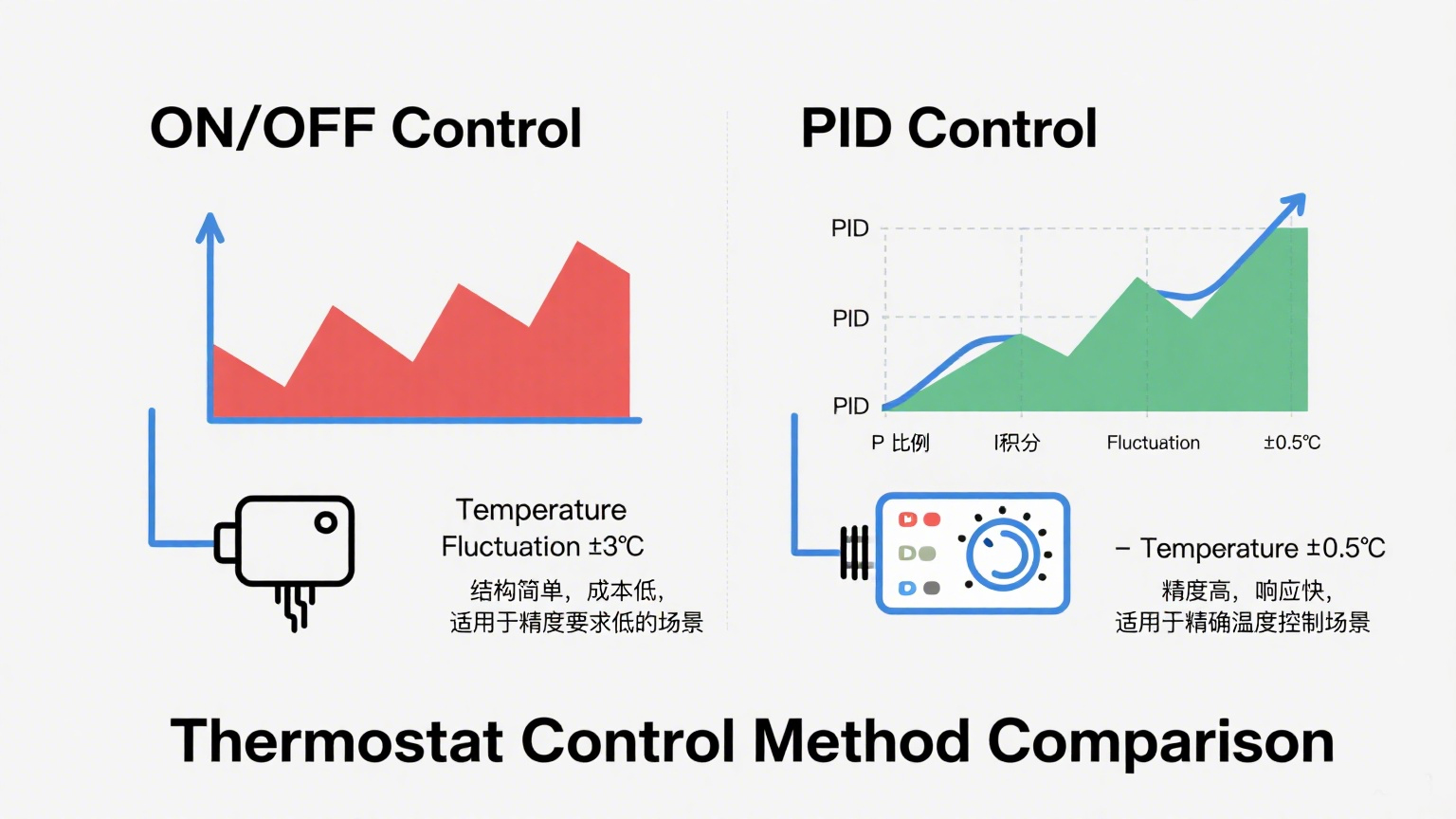
Common control methods include "switch quantity", which is generally connected to ON/OFF.
A more advanced method is PID control
There are only two fixed outputs. The one is "on" when the temperature reaches the actual temperature and "off" when the temperature is higher than the actual temperature. Full power and complete stop - commonly known as "on" and "off"
PID control mode (proportional-integral-differential control) :
Its output is continuously variable and dynamically adjusted according to the target value of the required temperature. Generally, it can achieve an accuracy of ±5%
3. Advantages and disadvantages of the two control methods:
ON/OFF control has low accuracy and frequent output fluctuations, while PID control has high accuracy and can be used in multiple scenarios, being particularly stable. Different scenarios are suitable for different control methods
In terms of application scenarios, ON/OFF control is suitable for some applications with low precision requirements: refrigerators, water heaters...
High PID control accuracy: suitable for industrial production lines, 3D printers...
4. Power load:
Power ÷ voltage = current. Generally speaking, the rated voltage for household use is 220v. When the voltage remains constant, the magnitude of the current is directly proportional to the power. For example: For a 2000w electrical appliance operating at a household voltage of 220v, the working voltage is =2000w÷220v=9.1A. It is necessary to select a temperature controller current with a rated load of 9.1A or more
Before the inspection, some auxiliary tools need to be prepared: screwdriver, wire stripper, multimeter, level, marker pen, insulating gloves, insulating shoes, flashlight
Safety prerequisite confirmation: Locate the main power switch, disconnect the power supply, conduct a voltage test, and check the line standards
Summary: Check the compatibility of the equipment. ① Refer to the "Technical Parameters" section and mark the key parameters with a marker for comparison; Scan the QR code on the product nameplate to enter the brand's official website and check the list of compatible devices. ③ Call the brand's customer service hotline and provide the models of both parties to confirm compatibility
Circuit Identification and Interpretation: Understanding the "Language" of Thermostats
The power supply is the "energy supply line" for temperature control.
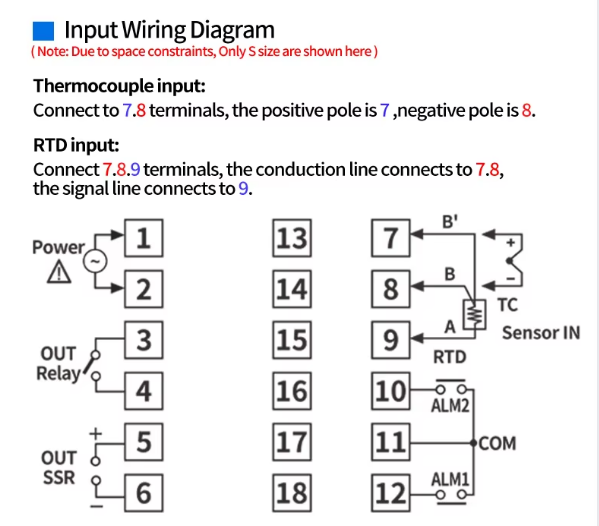
1. Common existing ones: live wire L, neutral wire N, bottom line PE
L; It is usually red, brown or yellow, connected to 220V AC voltage, and is commonly known as "phase line". IN the interface of the temperature controller, it is "L", "LINE" or "POWER IN". It needs to be directly connected to the power supply L. If it is connected in reverse, it will cause the temperature controller to fail to be powered on or have an internal short circuit and burn out.
N: It is mostly blue, black or gray, forming a circuit with the live wire, with a voltage of 0V. The interface is "N" and "NEUTRAL". For the temperature controller to work normally, it must be connected to the neutral wire to form a circuit with the internal chip's neutral wire. If the neutral wire has poor contact, it will cause the LED screen of the temperature controller to keep flashing and the function to fail
Circuit: The power supply starts from the positive terminal and then goes to the negative terminal, forming a complete path
Ground wire (PE) :
A yellow-green two-color wire, it serves as a safety protection wire, connecting the equipment casing to the ground. The interface is marked with "PE", "GROUND" or the grounding symbol (⊥). During use, the temperature controller and high-power equipment must be connected to the ground wire. When the equipment leaks electricity, the current can be conducted to the ground to prevent electric shock accidents.
The power equipment of the temperature controller must be connected to the ground wire. If there is a leakage, the ground wire will flow into the ground, thus avoiding electric shock accidents and ensuring the safety of the operators. It is strictly forbidden to use the neutral wire to replace the ground wire. Safety is the first step.
2. Temperature Controller has the functions of heating and cooling.
Load line: Control device "Instruction transmission"
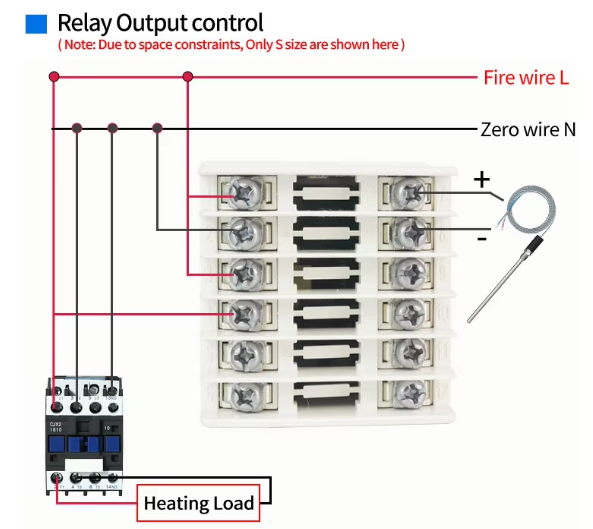
Heating load line: Controls the heating of the equipment. The interface markings are mostly "HEAT", "H", "OUT HEAT", and some brands use the numbers "1" or "2" - according to the manual. There is no mandatory standard for the wire color. It is usually the same color as the live wire or orange or gray. It needs to be connected to the heating input terminal of the temperature control equipment
Refrigeration load wire: Used for refrigeration equipment, marked as "COOL", "C", "OUT COOL", and the wire color may be green, light blue, etc. When the temperature controller switches to the cooling mode, it starts by sending a signal through the line and forms a loop control with the heating load line
3. Sensor: Mainly used for temperature perception
It usually has built-in or external sensor wires.
4. Control line: "Data Transmission Line"
There are generally: communication lines and interlocking control lines
Communication cable: Supports wired communication protocols (such as RS485, KNX), mostly two-core shielded wires (red and black), interface marked as "A/B", "DATA+/-" or (" RS485 "). The shielding layer needs to be grounded at one end to prevent communication interruption caused by electromagnetic interference. If the length of the wire exceeds 50 meters, a signal amplifier needs to be installed.
Interlocking control line: It connects other smart devices (such as door and window sensors, human body sensors), marked with "LINK", "interlocking" or device ICONS. The line color is mostly purple or gray. It realizes scene interlocking through switch signals (such as automatically turning off the floor heating after opening the door).
Post-connection inspection and debugging: Ensure safe operation
1. Interface tightness: Gently tighten the screws of each interface with screws to ensure that the circuits will not fall off due to certain issues during use
2. Rationality of circuit routing:
Organize the circuits inside the base box to prevent wires from crossing and entangling or being squeezed by the temperature controller panel. Reserve a certain length of wires, and the ground wire must be fixed separately to ensure the safety of the operators
3. Consistency of identification:
Compare the line identification recorded before connection (such as "L - Live Wire", "HEAT - Heating load") to ensure that the lines are connected in accordance with the instructions. Pay special attention to checking whether the live wire and neutral wire are connected in reverse to prevent equipment from burning out
Function debugging after power-on: Verify the control logic
Power-on startup: Turn on the power, observe whether the temperature controller is powered on normally, and observe the indicator light of the temperature controller. At the beginning, the temperature controller will light up and enter the initial optimization interface (usually within 3-5 seconds).
2. Anomaly Monitoring After powering on, listen carefully for any "sizzling" discharge sound, smell if there is any burnt smell, and touch the outer shell of the temperature controller with your hand to see if it is warm. Generally speaking, when the power is first connected, the temperature does not rise significantly. If there are situations such as the screen not lighting up, the indicator light flashing, or a circuit breaker tripping, quickly cut off the power supply and immediately check if the power voltage is normal and if there are any issues with the live wire and neutral wire It is essential to cut off the power supply in time to prevent any losses
3. Voltage stability:
Use a multimeter in the "AC 220V range" to test the voltage at the power interface of the temperature controller. Excessively high voltage can damage the internal electronic components, while excessively low voltage may cause functional abnormalities
5. Check the core functions of the temperature controller
Refrigeration and heating
Set the temperature controller to "Heating mode", and set the target temperature to be 10℃ higher than the current ambient temperature. Start the equipment, and the "HEAT" indicator light of the temperature controller will light up. When the ambient temperature reaches the target value, the equipment should automatically stop running and the indicator light will go out.
Set the temperature controller to "Cooling Mode", set the target temperature to 10℃ higher than the current ambient temperature, start the equipment, the "COOL" indicator light will light up, and it will automatically shut down when the temperature drops to the target value
Sensor sensitivity testing: Reducing errors
Built-in sensor test: Cover the sensor area of the temperature controller panel with your hand and observe whether the temperature displayed on the LED screen rises (normally, it should rise by 0.5℃-1℃ per second). After removing your hand, the temperature gradually returns to the actual room temperature.
External sensor test: For a thermostat with an external sensor, heat the sensor probe with warm water (avoid exceeding 50℃), and observe whether the displayed temperature of the thermostat changes synchronously. If there is no response, it indicates that the sensor wire is connected in reverse or there is a line fault.
Switch freely between heating, cooling and other modes, and observe whether the equipment starts and stops accordingly and whether the indicator lights switch correctly
After the debugging is completed, the final product can be used normally


