How to connect temperature controller
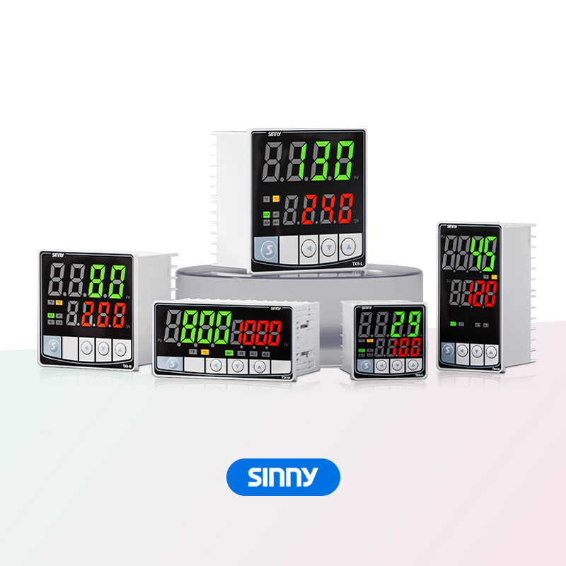
When we connect the temperature controller for operation, we usually involve the connection of power supply, temperature sensors, actuators and other parts, all of which play a very important role in thePID temperature controlsystem
Preparatory stage: Clarify core information and tools
The connection of the temperature controller should follow the core process of "safe power-off → clear wiring logic → step-by-step operation → power-on verification"
Preparatory work should be done in advance. Before connection, solve the problems of interface and where to connect first to avoid blind operation
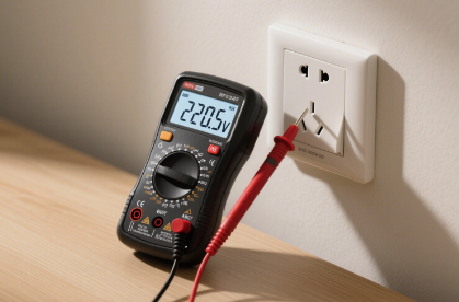
First, confirm whether the rated voltage of the thermostat is household voltage 220v or 12v DC, and whether the current and voltage are consistent with the equipment. Look at the terminals at the back of the thermostat to clarify the core function of the terminals. Generally, there is a wiring mark for the terminals beside the back. The live wire input (L) is usually red as the live wire, and the neutral wire input (N) is usually blue as the neutral wire. It is mainly used for the circuit of current signals, as well as the wiring of temperature sensors (S1/S2), and the NTC sensor wire that comes with the temperature controller (without positive and negative poles). It's best to prepare some screwdrivers, wire strippers, voltage testers and multimeters
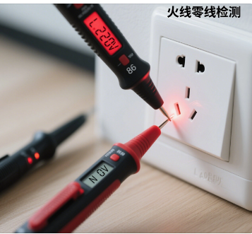
Step 2: Make sure to completely cut off the power and take proper safety precautions. Use a voltage tester to check the live wire and neutral wire to see if the tester lights up. If the tester lights up, it indicates that the power has not been cut off and there is a danger. Immediately cut off the power.
Then disassemble the shell. For the snap-on type: gently bend the front panel directly with your hand (apply force from the edge to avoid breaking the snap-on).
If it is a snap-on type, gently bend the front panel directly with your hand. It is best to apply force from the edge to avoid breaking the snap-on. connect temperature controller
Unscrew the small screws at the four corners of the panel. After removing the panel, expose the internal terminal block. Check the wiring ports carefully and it's best to make a record :
Mark the circuits. If you are afraid of forgetting, you can take photos to record it first. Make sure to confirm the relationship between the wires and the terminals. Then remove the wires one by one, mark the neutral wire, the live wire and the wires connected to the equipment. This will solve some problems in the early stage after the installation is completed
Part Three: It is the wiring operation
Look at the terminals and connect them according to the terminal definitions
Stripping: Remove the insulation layer of the wire to expose a few millimeters of copper wire. If the copper wire has burrs, gently twist it into a strand. Do not make it too long, otherwise a short circuit may occur. This point should be noted
Insert the copper wire into the corresponding terminal hole, then tighten it with a screwdriver, and then pull the wire to ensure it is stable and does not loosen
If the terminal spacing is small, insulating tape should be wrapped around the terminals and the connection points to prevent the copper wires of adjacent terminals from coming into contact and short-circuiting
Step 4: It involves organizing the circuits, assembling the casing, and powering on for verification
Make sure that all terminals have no exposed copper wires. Bend the circuit to prevent the wires from coming into contact with metal parts
The main body and terminal screws are fixed, and then the front panel is fastened
At this point, it's time to power on, and the functional test and temperature test will be completed


