


Understanding Analog PID Temperature Control
I. I. Introduction
B. B. Introduction to PID Control: Proportional Integral Derivative
One of the most effective and widely used control strategies for achieving accurate temperature regulation is the Proportional-Integral-Derivative (PID) control algorithm. The PID control algorithm calculates corrective actions based on the three components of Proportional, Integral and Derivative. The D-term predicts the future error based on how the error rate changes. Combining these three components, PID control systems can provide precise, stable, and accurate control while minimizing the size of error as well as the time required to correct it.
C. Difference between digital and analog PID controllers
Analog or digital PID technology can be used to implement the control. Analog PID Controllers use electronic components such as operational amplifiers (OA), resistors and capacitors along with potentiometers and other similar devices to generate control signals and perform mathematical calculations. Digital PID controllers, on the other hand, use software to run the algorithms. Digital controllers are more flexible, have greater diagnostic and programmability capabilities. However, analog PID controls remain an option for simpler applications, where robustness, cost effectiveness and stability in stable environments is a priority.
D. The purpose of this article is to explain analog PID thermostats.
This article aims to explain analog PID controllers in detail. This article will explore how the controllers work internally. We'll look at their main components, and examine their electrical operation. We will also discuss the advantages and disadvantages of analog PID temperature controllers compared with their digital counterparts. In addition, we'll examine typical applications in which they still are used, as well as provide advice on how to tune and maintain them. The reader should be able to understand what a PID analog temperature controller does, why they are preferred in some situations, and how it operates.
II. What Analog PID controllers do
A PID analog temperature controller is a loop of feedback. Basic principle: continuously measure the temperature being controlled and compare it to the desired setpoint. Calculate the error (difference) then generate an output signal that is proportional to the error. This will adjust the heating element or cooling device. We will examine the components of an analog PID control and how they interact.
A. A. Basic components: sensors, Summing junction, Proportional, Integral, and Derivative Elements
A PID analog controller is made up of several basic blocks. A temperature sensor such as a RTD or thermocouple is first used to determine the temperature of the object or medium being controlled. The sensor is used to convert the temperature of an object or medium into an electrical signal.
The sensor signal is fed to a summing circuit, which can be implemented by an operational amplifier configured as virtual ground (opamp), or differential amplifier. This summing circuit subtracts the sensor signal from the setpoint (which is the desired temperature) to produce the error signal. This voltage is proportional to the temperature difference.
Three separate circuits are then used to process the error signal, which corresponds to the PID components I and D. These circuits each calculate a control contribution based on an error signal.
B. B. Electrical signal processing: Amplifier, filter
Often, the raw signals of the sensor temperature and setpoint are too weak for the circuits to process effectively. In most cases, this is done by using amplification. Op-amps, which provide gain, are often used to achieve this. They ensure that the signal is within the range of the P, D, and I elements.
Filtering can also be used to filter the sensor signals, reducing the effect of noise. Noise at high frequencies can lead to erratic derivative calculation, resulting in unstable control actions. You can use simple RC filters (resistor/capacitor). They will smooth out the signal, before it enters into the D element circuit.
C. Relays, Solid State Relays or TRIACs
This final signal is formed by adding the outputs from all three calculation stages (often using another opamp). The signal represents the level of cooling or heating desired. The output of the controller is driven by this final voltage.
In many analog PID controllers, the output stage controls the element heating or cooling based on a control signal. Solid-state relays (SSRs) or Triacs are used in many analog PID Controllers to achieve this. In many temperature-control applications, SSRs have a higher switching speed and longer life expectancy (since there are no mechanical moving parts). They also tend to consume less power than mechanical relays. Mechanical relays are still available, particularly for applications that require higher power or where robustness is an advantage.
D. Explaining the feedback loop control mechanism in a simplified manner
Consider the feedback loop to understand how the system works: the temperature sensor measures current temperature (T_current). The measurement is then sent to the summation junction where it's compared with the setpoint temperature. Calculate the difference between T_setpoint and T_current (Error). The P, I and D elements then process this error signal to produce contributions (P_terms, I_terms, D_terms). This sum (Control Signal = Ki P_term + PI_term * Kd*D_term where Ki and Kd are gain constants), determines output state for the relay. The output controls the cooling or heating element which in turn affects the temperature of the process. This cycle of measurement, comparison and calculation is repeated continuously by the system to maintain the temperature close to desired setpoint.
III. The Key Components of Circuitry
Examine the electronic components that are typically used in analog PID controls and how they affect the algorithm.
A. Thermocouples and RTDs (Temperature sensors)
First, the sensor is responsible for measuring the process temperature. Most commonly used are Thermocouples (also known as Resistance Temperature Detectors or RTDs), and Resistance Temperature Detectors. Thermocouples are made up of two metal wires that have been joined together at one end. A voltage is produced at this junction in proportion to temperature. The resistance of RTDs is predictable and changes with temperature. They are typically made from platinum.
The input terminals of the controller must be wired up to these sensors. Sensor and controller designs determine the type and method of connection (e.g. BNC connectors for thermocouples and screw terminals or RTDs). For accurate temperature measurements, it is important to have the right wiring, and in some cases signal conditioning, such as cold junction compensation (for thermocouples).
B. B.
The summing amplifier is an important circuit that's usually built on an operation amplifier. The summing amplifier receives input from the sensor temperature (often amplified) as well as the input indicating the setpoint temperature. The sensor's reading is subtracted from the setpoint temperature to generate the error signal. The configuration could be either a simple summing inverter or non-inverting, depending on specific requirements.
C. Potentiometer with proportional gain (P) and its effects
Contribution of the Proportional term (P) to the final signal control is directly proportional to the magnitude error. Potentiometers are used to adjust the gain of the P-term, which allows the user to control how the controller reacts to the error. Higher P gains result in stronger responses (the output will change more rapidly for an error). This can cause temperature to rise faster, but it may also lead to oscillation and overshoot. A lower P gain will result in a gradual response that is less stable, but may take longer to reach its setpoint.
D. Components that prevent winding up and provide timing (e.g. capacitor, resistor).
Integral (I), on the other hand, eliminates the steady state error through the addition of the error signal to the output control. In most cases, this is implemented by connecting an RC (resistor-capacitor) circuit in parallel to the feedback loop on an Op-amp that has been configured as an Integrator. This RC circuit's time constant determines how fast the integral term accumulates. A diode can be used to prevent an integrator from building up excessive error signals (also known as "integral winding-up"), especially when close to the desired setpoint. The diode discharges the capacitor when the error sign changes, effectively limiting integral term contribution.
E. Calculation of derivative (D) using a differentiator circuit, or rate sensing element
This term, Derivative(D), predicts errors in the future based on how fast the error signal changes. It helps to reduce system overshoot and dampen the whole thing. For simple analog implementations, you can use a circuit that is based also on an Op-amp and RC component. Differentiator circuits can be sensitive to noise. This may cause oscillations and instability in the D-term. Simpler implementations could use a thermistor, or bandpass filters tuned to the frequency of expected temperature changes. This would allow the rate of change to be sensed in a more sensitive way.
F. Considerations for power supply
These electronic components all require an efficient and stable power source, which is usually provided by DC voltage sources. Power supplies must deliver enough current to all active components, and be properly regulated for consistent controller operation. Decoupling capacitances can be placed between the inputs and the outputs of the power supply for sensitive circuits, such as opamps. This helps to eliminate any noise from the electrical system.
IV. Advantages of analog PID controllers
The advantages of analog PID controllers are many, and they make them ideal for applications where reliability and simplicity are important.
A. A.
By their very nature, analog PID controllers have relatively simple electronic circuits. The controllers are made up of well-known components such as op-amps and resistors. The simplicity of the design leads to an easier process, and in many cases to less failure points. The basic idea of setting the temperature, reading the level and adjusting output are intuitive to operators. This means that they require less training than complex digital systems.
B. Real-time, continuous control action
Analog controllers generate continuous outputs and process inputs. Digital controllers sample the inputs at discrete time intervals, and perform calculations using software. Analog controllers don't do this. The continuous processing makes it possible to respond very quickly to temperature changes, making the control smoother.
C. C.
Analog PID controllers tend to be highly robust and reliable due to their simple design and the lack of microprocessors and software. Digital controllers are more susceptible to failures such as microprocessor crashes or software bugs. Analog controllers have less of a chance. Analog controllers are able to provide many years of service in stable conditions.
D. Cost-effective compared with sophisticated digital controllers
Analog PID controllers use components that are less expensive in general than microprocessors and memory chips. They also do not require sophisticated software or communication modules. Analog controllers are therefore a cost-effective option for those applications that do not require the sophistication of digital systems.
E. The intuitive tuning method (but potentially more trial and error)
Analog controllers are more intuitive for engineers who have experience with analog electronics. They can understand the basic principles of tuning an analog controller. Potentiometers are adjusted directly by observing how the system responds. This process is not without some error, but it can be intuitive to those who have the proper background.
V. V.
Analog PID controllers are not without their limitations.
A. Digital tuning is less precise and flexible than analog
Typically, tuning an analog PID control involves manually adjusting P, I and D potentiometers, while watching the behaviour of the system. Often, achieving optimal gains requires a lot of experience and many adjustments. In contrast, digital controllers can do sophisticated calculations and offer automatic tuning algorithms. They also allow for fine tuning through software and display graphical representations of control loop behavior. This makes the tuning process more accurate and time efficient, particularly with complex systems.
B. B.
Digital circuits use digital signals which are not as susceptible to interference. Analog circuits have a higher susceptibility to noise. Temperature changes, component ageing, and power supply fluctuations can cause analog components to drift. This leads to an overall loss in accuracy of temperature control. It may be necessary for regular calibration to ensure performance.
C. C.
The output port of an analog controller is usually limited to a single SSR or relay. Digital controllers have more input/output options and programmability. They can also communicate via networks, such as Modbus and Ethernet, accept multiple sensors, and control multiple outputs at once.
D. Difficulty implementing features that are advanced (e.g. cascade control or communication protocols).
Standard analog PID controllers are not capable of implementing advanced control strategies such as cascade controls (controlling a loop by using its output) or communication withShangWei Ji (supervisory computer) or with other devices in a network. Digital controllers have these capabilities due to their processing speed and programmability.
E. The setting of hysteresis is usually mechanical
In analog controllers, the hysteresis (the difference in temperatures between on and off) is set by a simple potentiometer or mechanical switch. These are usually located near the front of the device. It is less accurate or user-friendly than the digital options for programming hysteresis available on digital controllers.
VI. Application where Analog PID controllers are still used
Analog PID controllers are still relevant in many applications, especially where simplicity and affordability is important.
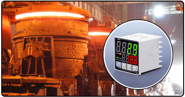
A. Heating/cooling industrial (furnaces and ovens)
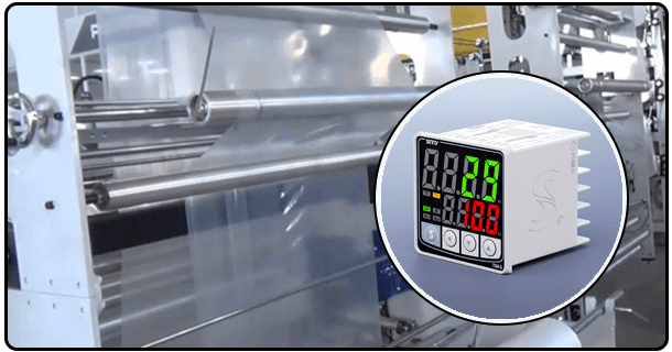
Many industrial applications still use analog PID controllers. These controllers are used to control the temperature of industrial furnaces, such as those for metal processing, drying and curing ovens, or tanks that heat liquids. These scenarios require precise temperature control, yet the complexity of the processes may not warrant a full-featured digital controller. Analog systems are a good choice because of their robustness, and they're also cheaper.
B. B. HVAC systems
For HVAC systems (Heating Ventilation and Air Conditioning), analog PID controllers can be used to control the temperature of a simple loop, like the heating or cooling in a smaller building, or for a zone or area within a bigger system. Digital controllers, however, are preferred for HVAC systems with advanced features such as multiple zones, control of economizers, and sophisticated optimization.
C. C. Laboratory equipment
Analog PID controllers are often used in laboratory environments for basic incubators to grow bacteria or cells, as well as water baths that heat samples. These applications require a constant temperature, within a range. Analog controllers are a good choice for this, as they are simple and cost effective.
D. Consumer appliances (refrigerators, freezers - simpler models)
Analog PID controllers may be used in some simpler consumer appliances such as refrigerators and older models of freezers. Modern appliances may use microcontrollers to manage energy and perform more complex control, but the PID principle can still be implemented analogically in simpler designs.
E. Control of processes in situations requiring simplicity and low costs
Many process control applications still choose analog PID controllers when the main requirement is reliable and stable temperature control with a reasonable cost. These include applications in aquaculture, agriculture, and niche industries where digital solutions may be considered unnecessary or too expensive.
VII. Tuning an analog PID controller
A PID controller must be tuned properly to ensure that it performs at the level desired. Untuned controllers may oscillate, be slow to reach their setpoint or not eliminate the steady state error. To tune an analog PID, adjust the P, D, and I potentiometers according to the response of the system.
A. Performance tuning is important for optimum performance
The controller will respond to deviations in temperature quickly, smoothly and without overshoot. This minimizes time required to stabilise the temperature (settling times) and makes sure that the system is operating as closely as possible to its setpoint (reducing steady-state errors). Good tuning will ultimately lead to increased process efficiency, improved product quality and reduced energy consumption.
B. Common tuning methods
There are several methods for tuning PID controls. Ziegler and Nichols provides systematic guidelines that are based upon the ultimate gain of the system (the gain when the system reaches the point where it is unstable) as well as the ultimate period of the oscillation. It is useful but requires that the system be brought to the point where it oscillates, which may be difficult or undesirable to do in reality. Analog controllers are more likely to use the trial-and error method. The method involves setting initial gains (often zeroing out the D and I gains initially and focusing only on the P), watching the response of the system to a change in load or setpoint, then adjusting P, D, and I gains according to observed behavior.
C. Potentiometers can be used to adjust the P, I and D gain.
The process of tuning usually begins with the proportional gain (P). Adjusting the P gain potentiometer while watching how your system responds to disturbances is a good way of starting.
- Article: Arduino PWM PID Temperature Control
- Agptek Temperature Controller-Precision Thermal Regulation for Differential Applications