


What Is a PID Controller and How Does it Work?
1. (Section Understanding the PID controller)
The PID control is an automatic regulator that minimises the error between a variable in a process (such as temperature) and the desired setpoint. This is done by calculating continuously three different terms, based on current error.
Proportional: The term responds instantly to errors. The output of the controller is proportional with the magnitude error. The higher the 'Proportional gain (Kc),' the stronger is reaction to current deviation. However, too much gain may cause oscillations.
Integer (I): The term is used to account for the error accumulation over time. The goal is to remove any steady-state residual error through the integration of error signals. This parameter, 'Integral Time' (Ti), determines the speed at which this error accumulates and influences controller action. A lower Ti indicates a quicker correction of past mistakes.
Derived (D): The term is used to predict future errors based on changes in the error rate. This term helps predict changes, and it can also improve stability through dampening oscillations. This parameter, 'Derivative Time' (Td), controls the amount of 'future action' based on rate changes. Noise can affect the derivative action.
This controller then combines the three terms calculated (P, I and D) into a single output signal which controls an actuator such as a heating system or cooling system. The P, D, and I parameters are essential to achieve optimal performance. However, accurate wiring is the key foundation that ensures controllers see the real process temperature, and correctly signal actuators.
2. The Key Components in Temperature Control PID Wiring
(Section: Key Components)
Be familiar with the basic components of a temperature control system before diving into specific wiring:
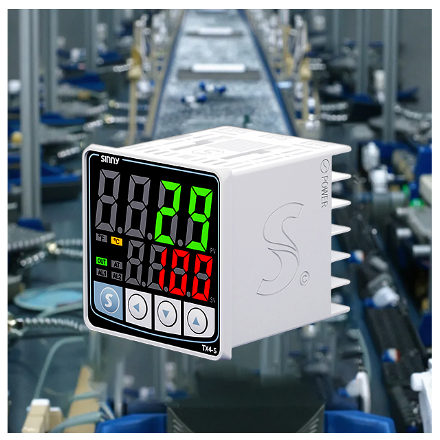
PID controller: It is the brain of the system. The PID controller measures temperature, compares that to the setpoint and calculates its output parameters. It then sends an output signal to a device.
Inputs Intended for sensors such as thermocouples or RTDs. Some models can accept voltage and current signals.
Outputs: A relay is used to control the power supply to cooling/heating elements. Some controllers feature 0-10V outputs and communication ports.
Input Power: This is usually a DC voltage of low intensity (e.g. 12-24V), or AC power.
Interface/Display: Features an LCD display and buttons to set parameters, view status and enter auto-tuning mode.
Sensor of temperature: A device which measures actual temperatures. Some of the most common choices are:
Thermocouples Reliable, large temperature range and relatively cheap. The thermocouples produce a voltage that is proportional to the temperature. The characteristics of the different types (e.g. J, K, and E) are also varied.
Resistance temperature detectors (RTDs). Provide greater accuracy and stability, particularly at lower temperatures. The electrical resistance changes with temperature. They are commonly used.
Thermistors High sensitivity, rapid response but usually limited to smaller temperature ranges. Due to their nonlinear response, they are commonly used in digital temperature meters.
Final Control Element/Actuator: Device manipulated by controller for temperature change. It could be:
3. Heating Elements: Heater, water heater, and boiler.
Cooling Element: Chiller, fan, Peltier cooler.
Valves: Flow control of heat/cooling fluids.
Output Device/Relay A solid-state or electromechanical relay, usually located inside or outside the PID controller. The controller output signals are used to switch the power on or off. The relays have three contacts: Normally Open (NO), Normally Closed (NC), and Common (COM). They require care in wiring so as to prevent damage caused by motors, solenoids, or other loads that are magnetic.
Power supply: Supplies the required voltage to the PID controller system and actuators.
How to connect the temperature sensor to the PID controller
(Section : Sensor Wiring Diagram)
It is the part that has the greatest impact on the control system, since inaccurate readings of sensors can lead to poor performance.
Resistance Temperature Detectors
The RTDs are very accurate and resistant to changes in resistance of the lead wire. These devices require constant current for excitation.
Wiring Connect both sense leads, usually designated as RTD A and B in parallel with the excitation (RTD C), to complete the circuit. The controller will determine the exact polarity based on its internal circuitry, but it typically measures voltage across RTD sense lead. Consult the manual of your controller for details on pinouts and excitation. A wiring diagram often helps.
Importance By using a 3-wire configuration, you can compensate for variations in resistance caused by the length and temperature of lead wires. The wrong wiring of a circuit can cause significant measurements errors.
4. Thermocouples
Thermocouples produce a voltage that is based on the difference in temperature between two junctions. (Hot junction, the sensor tip; cold junction, usually an internal or external standard). The range is much greater, but the sensitivity lower than RTDs.
Wiring Connect two wires of the thermocouple leads with the terminals corresponding to the PID controller thermocouple input. doesn't matter what polarity is. The controller, or an Omega Engineering reference such as Omega Engineering will specify the correct way to connect the (+) and (-) positive leads. Certain controllers automatically detect polarity.
Cold Junction Compensation: The majority of modern PID controllers measure and compensate thermocouple values based on internal measurements. Make sure the thermocouple is representative of process temperatures and that it's not being heated by other sources.
(H3 Heading)
Thermistors
Thermistors are commonly used as digital thermometers. They exhibit an extreme change in resistance when temperature changes (negative temperature coefficient, NTC).
Wiring Is typically connected via a voltage-divider circuit, or in current-sensing configuration. Specific wiring is determined by the input type of the controller (voltage measurement or current measurement).
Considerations Temperature and resistance are not linearly related. For accurate temperature control and display, calibration or lookup tables in the controller is usually required.
Connection of an analog voltage/current input (less common for direct temperature)
Some PID controllers are capable of receiving a direct voltage signal (0-5V or 0-10V), or a current signal (4-20mA), from an external transmitter or sensor conditioner. The sensor circuitry is bypassed.
Wiring : Connect in accordance with the voltage range or current range. Verify the correct polarity of voltage signals. Consult the manual of your controller for settings such as input type and range.
5. How to power the PID controller
(Section: Controller Power)
The majority of standalone PIDs need a separate supply to operate at low voltage.
Wiring: Connect your power supply to the terminals designated as 'Power In,' 'Vcc,' or other similar terminals. The manual will specify the range of voltages.
Important: Make sure the power supply is able to deliver enough current for both the controller, and any displays or interfaces connected.
The Relay output is connected to the actuator.
(Section Output Control).
Relay outputs are the interface between intelligent PID controllers and physical elements (heating/cooling).
Wiring: Connect the relay output terminals of the controller (typically "COM", "NO", or "NC") to the control circuit for the actuator.
Common (COM): Connects the positive (+) terminal of the power supply to the actuator or load.
No (Normally open): This terminal is connected to COM when the relay (output signal activated) is powered. The circuit then goes to the actuator. Heating is usually activated in this way.
NC: This terminal is connected to COM when the relay de-energizes. This terminal is often used to control safety interlocks and cooling circuits.
Example: Controlling a heater requires a positive power source.
Connect the positive (+) terminal of the actuator to the "NO" terminal.
Connect the negative wire (-) of the actuator to the terminal marked 'NC.
Connect the "COM" terminal to the negative wire (-) of the power source.
Connect the positive (+), wire from the power source to the relay output input of the PID controller (usually via jumpers or terminals separate). Refer to the controller's manual for information on relay output wiring.
Important: Usually, the power to run an actuator (heater or motor) comes from another source. The output of the PID controller is used to control, the relay. This then controls the high-power supply for the actuator. It is not recommended that the controller directly handles high-power cables unless it has been specifically designed to do so (rarely for PID controllers).
Safety: When switched, inductive loads such as relays and motors can produce voltage spikes. Flyback diodes (diode between the load and the power supply with the cathode facing the load) protect the coil of the relay from harmful back EMF. This is usually built into controller relay circuits. Always follow the safety protocol when wiring high voltage mains power.
6. Connection of an Analog Input: Less common Scenario
(Section: Analog Input)
A few PID controllers can be connected to an external voltage/current signal as a feedback input or setpoint.
Wiring Connecting the Signal Source (e.g. another sensor transmitter, or a Potentiometer), according to specified voltage range or current. Refer to the manual for details regarding input impedance.
Powered Actuator System
(Section Actuator Power).
Power required by the actuators (heating elements, motors, etc.). The power required for an actuator (heating element, motor, etc.) is typically much higher than that of a controller with low voltage.
Wiring Connect directly the power leads of the actuator to the power supply that is appropriate (mains voltage if the device has high power, or lower voltage if the device requires it). PID controller relay output switches between power supply and actuator. (See relay section for details).
Take into consideration: Use wiring and connectors that are rated appropriately to deal with the voltage and current of the actuator. Make sure the actuator size is correct for your application.
It's all about the wiring and tuning of PID loops
(Section Tuning & wiring)
Tuning Requirement: You must first ensure that your controller receives an accurate, stable temperature reading of the process and that it is driving its actuator relay with the correct output signal. Before you dive into more complex tuning methods like Ziegler Nichols bump tests or the auto-tuning feature of the controller, start with the basic wiring check. Refer to Control Engineering's detailed tuning methods.
Safety Considerations
(Section Safety First)
7. Electrical systems require caution when working with them.
Disconnect the power: Before working with wiring or high voltage circuits, always disconnect the main supply.
Check the polarity of all power supply, sensors and actuators (especially thermocouples) to ensure that they are in the correct direction. The incorrect polarity may damage or malfunction equipment.
High voltage: Use extreme caution when working with power sources or actuators that are powered by mains current. Wear the appropriate PPE and lockout/tagout procedures, if needed.
Heat Heating components can get extremely hot. Let components cool down before handling.
Limits for components: Make sure all your component (wires and connectors), sensors, actuators or relays are suitable to the voltage, temperature, current range, etc. of the application.
Refer to manuals: Always consult the wiring diagrams, safety datasheets, and other documentation provided by the PID controller.
(Conclusion)
- PID Temperature Control Algorithm Industrial Implementation and Optimization Guide
- The PID Setting for Temperature Control Tuning Guide and Industrial Parameters