


What is the PID temperature controller? A Comprehensive Guide
I. I. Introduction: Precision Control and the Imperative of It
use, and solve problems with these devices if you understand the "how".
II. The Core Components Unpacked: What Is a PID Control?
The PID controller maintains a variable process (such as temperature) within a set point with great precision. It's important to understand the capabilities of its components.
Process: Here is the control system. The process in our context is usually a cooling or heating system such as an water bath or chemical reactor. We are interested in the temperature.
Sensor: Measures the temperature of the processing. Sensors include the following:
Thermocouples They are made of two metals that have been joined together at one point (the measurement junction). The thermocouples generate a voltage that is proportional to temperature differences between a measuring junction and the reference junction. These are rugged, inexpensive and can be used for a large temperature range. Cold junction compensation must be performed by the controller.
Resistance temperature detectors: Their electrical resistance changes with temperature, just like Platinum RTDs. These sensors are more accurate and stable than thermocouples and they're often used for laboratory or high precision applications. Signal conditioning is required (e.g. using an integrated circuit or Pt100 module). There are other types, but they're less common in standard PID controls.
Controller: It is the "brain" of the system. Analog controllers have traditionally used circuits that included operational amplifiers and capacitors in order to execute the algorithm. Most modern controllers use digital and a microprocessor (MCU) for calculations. It allows greater flexibility and programmability. This controller takes the raw sensor signal, converts it to digital (A/D or Analog-to Digital), runs the algorithm and then generates control signals.
Final control element (Actuator). This component is the final controller and receives the signal from the digital thermostat. It then takes action physically to affect the process temperature. Actuators include the following:
Solid State Relays: Electronic switch that turns power on and off to heating elements based on control signals.
Outputs of Power Transistor: Used for varying the amount of power delivered to resistive heating elements (e.g. a power resistance or heating coil).
Relays Mechanical switch that switches high-power circuits using a control signal of low power (often in combination with other actuators).
Solenoids Valves: Used to regulate the flow of refrigerants and coolants in cooling systems.
III. The core concept: Bridging Gaps between Setpoint Temperature and Process Temperature
A PID controller's fundamental objective is to reduce the temperature difference between the setpoint temperature and actual temperature. This difference is known as the Error Signal. This error is calculated by the controller, which continuously monitors and measures the temperature of the process, compares that to the setpoint.
Cycle of Measurement: Using its input circuit, the controller receives the temperature sensor's signal. The circuit is responsible for signal conditioning, amplification and filtering (such as cold junction compensation in thermocouples, or linearization of RTDs).
Calculation of Errors: In a digital control, the digital processor converts conditioned signals into temperature values. The measured temperature is compared with the user-defined setpoint. The result of this comparison is the Error Signal: Setpoint = Measured Temperature.
The pid algorithm is at the heart of controller intelligence. The controller uses the calculated signal to generate an output for the actuator. It's important to note that this output does not simply react to the error at hand; rather, it is a complicated calculation that takes into account the past history of errors.
IV. The Mathematical Heart: Breaking down the PID Algorithm - Proportional Integral and Derivative
The algorithm is a combination of three terms that each respond differently to the signal. It is important to understand these components in order to fully grasp how PID controllers achieve precise control.
Control proportional to (P):
Principle: The proportional control responds instantly to the present magnitude of the error signal. Control action is proportional with the error.
Mathematical representation: Calculate the output of the P component as: Output_P = Error where Kp represents the proportional gain. proportional bands are also used to express the output. A smaller PB indicates a higher Kp. If the error was 5degC, and the Kp value is 2, then the output of the P component might be 10 units. (The actual meaning will depend on the output range for the controller, such as 0-100%, or 0-20mA). The P-component is large when there's a big error. This drives the actuator to work hard in order to correct it.
Benefits: Responds quickly to initial changes in process temperatures or setpoints.
Disadvantage: The proportional control only responds to current errors, leaving a residual offset. If the setpoint temperature is 100degC but it stabilizes around 98degC the P-controller stops applying the full correction, however the temperature will never reach the setpoint.
Control Integral:
Conception: Integral Control reacts over time to the accumulation of errors. The aim is to remove the residual offset caused by the P-action, by continually summing the errors.
Mathematical representation: The output of the I component can be calculated by: Output_I = Error * Ki, where Ki is integral gain. This integral term adds up the errors over time, and then applies a corrective action proportional to that sum. The integral term increases if the error continues, forcing the actuators to work longer or harder until it is zero.
Integral Windup: An issue can occur if an actuator is unable to reach the desired position. (For example, the relay may be fully turned on but the temperature of the process is too low). Integral windup is a condition where the integral term accumulates and can reach a limit. It can lead to long delays if the correction is needed. Modern controllers use anti-windup techniques.
Benefits: Reduces the error associated with proportional controls, which is often caused by the "steady-state" ( offset). This leads to a much more accurate adherence to setpoints.
Disadvantage: May cause an overshoot when the temperature is higher than the setpoint and may slow the response overall if integral actions are too aggressive. This also needs careful tuning.
Derivative (D) Control:
Conception: The derivative control is based on the change rate in the signal of error. The system predicts errors by analyzing how fast the current error develops.
Mathematical representation: The output of the D component can be calculated by: Output_D= (Kd* d(Error),/dt), Where Kd is derivative gain, which is often related to the derivative time Td. The term has a "braking" effect. The D-component adds resistance to the system if the error increases rapidly (temperature rises too quickly towards the setpoint). If the error decreases rapidly, this provides a small boost in order to combat system inertia.
Benefits: Increases stability and reduces overshoot.
Disadvantage: The derivative action is sensitive to noise (caused by electrical interference or drafts) in the temperature signal. It is sometimes necessary to filter the input signal. The filter has no impact if there is a constant error (no matter how large).
Combining the three elements P, I and D. This is the final output sent to the actuator. Output= Output_P plus Output_I plus Output_D. Weighting factors are tuning parameters which define the nature of a control action. tuning is the process of finding an optimal combination.
How to Control a PID Thermostat (Putting the Theory into Practice).
It's one thing to understand the components, but another to see how they interact in an actual system. This is a detailed overview of the cycle.
Measuring: Using the sensor connected, the controller measures the temperature. A thermocouple, for example, generates voltage which the controller then converts to a reading of temperature.
Calculation A comparison is made between the measured temperature and the Setpoint. The controller calculates error signals. The algorithm calculates P, I and D components based on current error and history (for I) and rate of change (for D).
Actuation: Calculate the amount Control output A combination of P I D is sent to final control element. It could be:
Increase the power of a heater element.
Reduce the power of a heater element.
A cooling device (such as a refrigerator or fan) is activated.
Adjusting the locati0n of a temperature-control valve.
Constant Cycle: This process is repeated almost instantly (often thousands of times per second). The controller continuously monitors temperature and calculates necessary actions. It then adjusts actuators accordingly. The feedback loop is quick, ensuring that the temperature of the process stays near the setpoint.
VI. The influence of the operator on manual versus automatic control modes
The modern PID controllers offer both automatic control (auto), and Manual (man) modes of operation to give the operator more flexibility.
Auto (Automatic) Mode: The PID algorithm runs in automatic mode. The controller sends to the actuator the output required based on the current error signal. It is the default operating mode to maintain a constant temperature without operator involvement.
Mode Manual (Manual): You can also find out more about the following: Manual control The operator can directly influence the output signal. In most cases, the output signal is controlled by an operator. bias You can also find out more about manual setpoint Value is entered. It still displays the temperature of the process, but ignores it when calculating output. Only the bias value entered manually determines the output signal. The following applications can benefit from this mode:
Make precise adjustments prior to switching on automatic control.
Directly controlling the actuator to troubleshoot.
Perform specific tasks such as a ramp up or down.
Temporarily overriding automatic control
VII. Tuning the PID controller (Achieving optimal performance)
The most difficult part of using a PID control is finding the balance between P, I and D. A poor tuning can lead to slow response, oscillations or instabilities. A good tuning will ensure precise, reliable control.
What Is Tuning? The process of tuning is to find the best gain (Kp Ki Kd), or the equivalent tuning constants PB Ti Td for a particular process.
Importance It is important to tune the system in order to achieve desired performance metrics such as response time, settle time, minimum overshoot and stability. This directly affects energy efficiency and the quality of products.
The tuning methods:
Open Loop or Closed Loop (Ziegler Nichols): A typical starting point is to increase the gain proportional, until the system oscillates. Then using certain rules you can calculate the initial tuning. It is important to observe the system carefully.
Autotuning Software: Most modern controllers come with autotuning functions. They perform various tests (such as a relay test, or an analysis of process response), and then automatically calculate the recommended tuning parameters. It simplifies things, but it may be necessary to understand the results.
Auto-Tuning Relay: Advanced controllers can use an integrated relay to create controlled oscillations and then measure system characteristics in order to find tuning constants.
Analytical methods: Mathematical models are used for simpler processes to determine optimal parameters. However, this method requires advanced knowledge.
Process reaction curve method: This involves manually setting the setpoint, plotting process responses and determining parameters to tune.
Factors to consider: The tuning of a process is heavily dependent on its dynamics (inertia or time constants and delays), as well as the particular processes. Other factors like noise from measurement and other disturbances should also be taken into account. Autotuning or trial-and-error are often used to find a starting point, which is then fine tuned based on the observed performance.
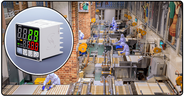
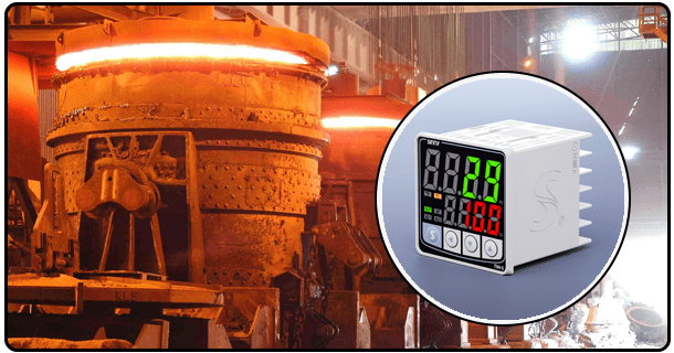
VIII. Application of PID temperature controllers in real-world situations
PID is a versatile and precise control that can be used in a wide range of applications, especially when temperature stability matters.
Laboratory research: The PCR machine requires precise thermal cycling. Incubators need to be stable for cell cultures. NMR spectrometers require controlled environments. Calorimeters accurately measure temperature changes.
Manufacturing Industry: The chemical reactors require precise temperature profiles. Autoclaves depend on steam sterilization. CIP/SIP Systems need to be cleaned and filled at controlled temperatures.
- How to configure and connect a PID controller.
- PID Digital Temperature Control with PT100 Input for Modern Applications