


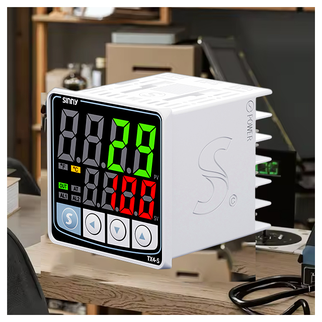
How to configure and connect a PID controller.
This guide includes information on sensor wiring, actuator controls, power connections, PID tuning and testing for temperature control.
1. Introduction
The PID controller uses an algorithm to calculate the necessary correction and apply it to the final control element, minimizing error. The PID temperature controller uses a complex algorithm that combines Proportional (P), Integeral (I) and Derivative actions to calculate and continuously apply the correction to the control element. This minimizes error and ensures stability. The first critical step to maximizing the capabilities of a PID controller is correctly connecting and configuring it. The guide takes you through the complete process of sensor connections, actuator controls, power supplies, configurations, testing and troubleshooting. It draws on established principles to guarantee a successful implementation.
2. Basics of PID Temperature Control
This difference, or "error," is what you call it.
Proportional Action(P): The component that adjusts output according to the magnitude of error. The output is adjusted based on the magnitude of an error. A big error will result in a larger adjustment while a little error will lead to a smaller one. The proportional control reduces the error quickly, but leaves behind a residual (offset) error.
Integral action (I): The integral action takes into account the cumulative error. The output is continuously driven to remove the residual error from the proportional action. This component remembers past errors, and makes adjustments to the output in order to reach the setpoint.
Derived Action (D), The part that reacts on the change rate in the error. The Derivative Action applies an appropriate force to the system if the temperature changes rapidly.
3. Laying the Foundation for Your Connection
Planning is the key to a successful connection. This stage should not be rushed as it can result in incorrect wiring and configuration, damage to equipment, or safety concerns.
Define Your System: Define the process or system whose temperature requires precise control. What is the normal temperature range? What accuracy is required? How much thermal mass is required and how long does it take for the system to respond? The controller and actuator specifications are determined by this information.
Choose the right controller: PID controllers do not all have to be equal. Take into account factors such as:
Control algorithm: Does this controller have a standard PID or advanced algorithms? (i.e. Smith predictor and filter options) Or does it offer anti-reset protection against windups.
Input types: Ensure that the controller is capable of accepting the sensor signals you intend to use.
Which output type will you choose? There are many options, including Solid-State Relays for fans or heaters, Relay outputs that control solenoids or contactors, Pulse Width modulation (PWM), outputs used to direct control fan speeds, and Analog Voltage/Current for interface with other devices or controllers.
Communications: Is the application requiring communication for monitoring, logging, or integration with a larger system (e.g. Modbus RTU/TCP/Profibus, Ethernet/IP, etc.)?
Interface and Display: Which level of interface do you need?
Calibration is a consideration: Initial calibration may be required depending on the requirements of the application and the state at which the sensor/controller was initially installed. This will ensure that the readings are accurate and control can work properly.
Bridging the measurement gap: Connecting the temperature sensor
Temperature sensors are the "nose" of the controller - they measure the temperature. Thermocouples, such as Type K, E, J or KJ, and Resistance Temperature Sensors, Pt100, Pt1000, are common industrial sensors.
Locate sensor input terminals: Locate the designated input Terminals on the PID Controller Panel, which are often marked "IN", "THERM", or "RTD".
Determine Sensor Type: Be sure to identify the type of sensor that you're using. This type of sensor must be configured in the controller.
Refer to the wiring diagram: Consult the manual of the PID controller and the accompanying wiring chart. The diagram will tell you how to connect the terminals and what type of connection is required (e.g. four wires for RTDs or three for standard thermocouples). It also shows the polarity and any other information that is needed.
Thermocouple Ex: Typically connect using specific connectors, e.g. BNC, DB9 or screw terminals. This diagram shows which wires connect to each terminal, and whether cold junction compensation has been built-into the controller (common with benchtop controllers) or requires an outside sensor.
Example of RTD: Can require up to four wires, depending on whether the sensor element is used and how it's excited. Wiring diagrams will detail the proper connections for accurate resistance measurements.
Securing the Connection: Trim the sensor wires and insert them in the terminals. Tighten the screws. To prevent short-circuits, ensure that the connection is secure and well insulated. If terminal blocks are available, use them. Avoid direct screw connections for greater reliability.
Calibration Test (Optional, but Recommended): Perform a basic test after wiring if you are able to access a temperature source that is known and have a thermometer calibrated. Verify the temperature displayed by the controller against the calibration. Minor adjustments may be possible depending upon the calibration capabilities of your controller.
Executing Control Command: Connecting to the final control element (Actuator).
It is "the muscle" of the entire system. The PID receiver adjusts process temperature based on the signals received from the PID.
Identify Actuator: Determine which device is going to adjust the temperature. (e.g. a heater controlled by relay or a fan controlled via PWM).
Locate the Output Terminals Look for the output terminals of the PID control, which are often marked "OUT", "AO" or "DA"(Digital/Relay/Analog) Outputs.
Make sure the output of the controller matches that of the actuator: Be certain the output type is the same as the input requirement.
Analog output (AO/DA).
Digital/Relay output (DA): Used for switching power to devices such as contactors and relays, which then control large loads. Attention should be paid to voltage ratings (e.g. 5V logic or 24V relay coil), and the wiring configuration (e.g. Normally Open (NO) vs Normally Closing (NC). It is important to set the controller output correctly (e.g. pulse length and duty cycle).
Wire an Actuator: Install the actuator in accordance with its datasheet. If you are using relay outputs to switch devices, make sure that the device is properly wired in between the NO/COM (or NC/COM depending on the application) terminals of the output and the source power. Connect the input wire of the analog actuator to the signal wire coming from the controller.
Set the output range and scale: Open up the configuration menu of your controller (normally via a LCD screen or buttons). Navigate to output and adjust the parameters to suit your actuator. Set the output range (e.g. 0-100%, 0-10V), and make sure it corresponds to the operating range of the actuator.
Connecting power to the controller: Energizing System
A stable supply of power is required for the PID to work. Wiring incorrectly can lead to serious danger.
Locate the Power Input Terminals. Look for the terminals "AC IN", VAC, or other similar terminals located on the back or side of the controller.
Connect the terminals of the controller to the power source (Live, Neutral and Ground). The wiring diagram is in the user manual.
Connect the power supply, which is usually the fused cable from the AC main power.
Safety & Polarity: Check all connections. Before touching any wires, ensure that the electricity is turned off. Check the phase of AC power (L1/L/N/G). The controller can be damaged by incorrect polarity when using DC power.
Tuning Algorithms for the PID controller
The controller's intelligent comes alive during configuration. Attention is required at this step.
Configuration Mode Access: Enter the programming mode using the keypad or buttons on your controller, or by using a PC-interface software. This can be indicated with specific LED patterns, or by a change in display mode.
Setup of initial PID parameters (tuning): Often the most complicated part. Often, initial parameters need to be adjusted ("tuning") Autotune or "Auto Tune", a feature of many controllers, performs an automatic test, which involves a change in the setpoint (often with a small step) to observe how it responds. It then calculates P, I and D values. Refer to manual PID tuning resources (such as the Ziegler Nichols method) if you prefer or need it. Adjust incrementally, starting with conservative values. Monitor the response of the process (minimal overshoot and quick settling). It is important to tune the control system in order to achieve a stable, responsive and oscillating-free process.
Output filter and dampening: Certain controllers have an output-filter setting that smoothes out noise signals coming from sensors, which prevents erratic actions. Some controllers have dampening functions that can reduce hunting or overshoot (small oscillations near the setpoint).
Bumpless Transmission: Configure bumpless transmission if the controller is capable. This allows you to change the parameters or setpoint without having the signal jump suddenly. It could cause overshoot, or even damage your system.
Save Settings and Exit: After configuration, make sure settings are stored in the memory of the controller (check your manual to find out the exact save command). Exit the configuration mode.
Verification and Testing: Validating Performance
It is important to test thoroughly after physical configuration and connection in order to ensure correct performance and verify the operation.
Visual inspection: Check all wires for insulation, correctness and security.
Power up: Replace the fuse or breaker at the power source.
Initial Response Monitor: Look at the display of your controller. Is it showing the right temperature?
Closed loop control: Modify the Setpoint (SP). Watch the response of the system. Is the system able to reach the setpoint accurately? Is it accurate? Are there any excessive oscillations or overshoots around the setpoint? Watch the approach rate and stability.
Final Tuning: If necessary, fine-tune the parameters of the PID based on initial performance. For optimal performance, minor adjustments may be required. This is especially true for Integral Action to reduce steady-state errors and Derivative Action to increase stability.
Data Logging (Optional). If your controller has data logging capabilities, you can enable the data logger to log temperature data and output control data. It can prove invaluable in analyzing the performance of your system and for troubleshooting.
Common Problems and Troubleshooting: How to Solve them
Even with careful planning, problems can still arise. Here are some symptoms that may occur and their potential causes.
Temperature Not Changing / Controller Output Not Active:
Verify that the setpoint has been set properly and is within the range of the process.
Check that the output configuration is compatible with the actuator requirements.
- led pid digital temperature controller
- What is the PID temperature controller? A Comprehensive Guide